

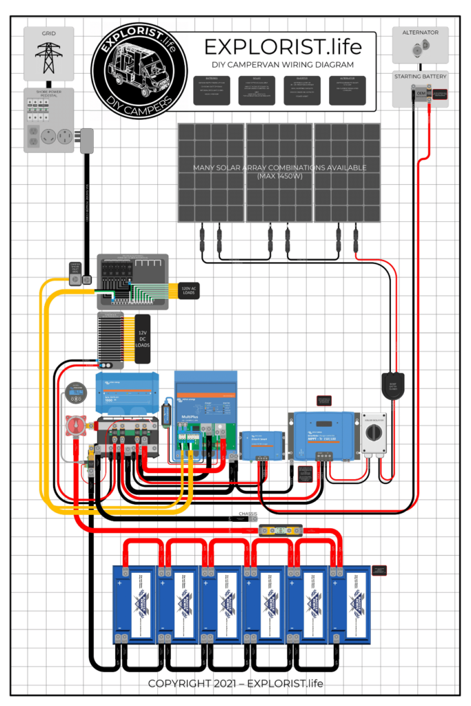
This DIY camper solar wiring diagram and parts list is perfect for ground-up electrical installs into campervans, skoolies, or expedition vehicles. This system is most suitable for systems that do not have a pre-existing house electrical system installed.
This diagram features:
- 3000W Inverter Charger
- 400+ Amp Hours of Battery Storage Capacity
- 400W-1450W Solar Array Capacity
- Alternator Charging
- Shore Power Charging/Passthrough
Not quite what you are looking for? Check out other system setups here: https://www.explorist.life/solarwiringdiagrams
History of Changes to this Page (Click to Expand)
Changes Made Oct 15th, 2022: Added links and advertisement to purchase parts through the wiring kits at https://shop.explorist.life Keeping the parts list to amazon up to date has been a pain point, and by offering the parts (from the screws to the components) directly from us, we can keep up with our parts in stock and quality control.
Changes Made Nov 28th, 2021: MAJOR UPDATE. Updated diagram to add more detail to the individual parts (labels on lugs, heat shrink, etc). Also added a pg 2 to the high resolution diagram to include the system from the following video: https://youtu.be/01F4QDVJUq0 There are very minor details changed between the two pages except for the solar array. Added seperate AC and DC distribution boxes as we have started sourcing those and selling those in-house so sourcing bottlenecks should no longer be an issue. Updated parts lists to include the EXPLORIST.life wiring kits.
Changes Made July 17th, 2020: Changed main DC Distribution busbars to be the Victron Lynx Distributor system instead of the EXPLORIST.life busbar. The EXPLORIST.life busbar is still available to be a DIY solution but I simply could not keep up with the demand for making these. Building busbars was taking up so much time I was having to neglect producing more videos and blog posts, which is what EXPLORIST.life is really about. The Victron Lynx Distributor is an all in one DC distribution unit that houses the fuses, positive and negative busbars needed to take the power from your battery bank to your individual main components. This product is an EXTREMELY elegant solution I think you will be very happy with. I also added an inline fuse and fuse holder between the battery bank and Victron Lynx as well as an inline switch. If you have any questions, as always, leave them in the comments below.
Changes made to diagram July 8, 2020: Changed equipment case ground wires to daisy chain back to the negative busbar instead of each having their own individual runs all the way back to the negative busbar. This results in less wire used, less clutter, and more free space at the negative busbar. I also removed the 300 amp terminal block at the house battery in favor of a 400 amp ANL fuse attached to the busbar. The 300 amp terminal block is adequate but I have heard of isolated events of this fuse blowing prematurely. When a 3000w Inverter is running at full capacity, it could be pulling near 250 amps. At surge capacity and heavy DC loads from around the camper, it’s possible the 300 amp terminal fuse could blow under normal, safe operation. If you are reading this and already have a 300 amp terminal fuse attached to the house battery bank; you do not need to replace it UNLESS it starts blowing prematurely. Finally, the 50A terminal fuse attached to the house battery bank protecting the wire going to the battery to battery charger was replaced with a 60A terminal fuse as I could not find a 50A terminal fuse in stock. If you have a 50A terminal fuse in that location, that’s completely fine and you need to make no changes.
Changes made to the parts lists July 8, 2020: A complete audit of all of the parts on this page was performed. Supply chain issues took a toll on this page recently and left many of my links incorrect. I have found a way to keep up with my links in a much easier way I have been doing in the past which means the links on this page should be MUCH more accurate going forward. Also, I added MULTIPLE different solar wiring examples to the bottom of this page so you can choose which solar configuration suits your own needs rather than providing a crash course in solar array design as that was proving to be too complex and therefore leaving the ‘done for you’ nature of this blog post lacking.
This page was originally published February 27, 2020
Thanks for your patience with these changes. I’m constantly trying to find better ways to teach this stuff and these parts lists and diagrams will be continuously optimized over time. -Nate
HOW TO USE THIS PAGE – VIDEO
This orientation video will show you how to best use this page to build your DIY Camper Solar Setup. It’s a quick watch but I think it’s pretty important.
DIY Camper Van Wiring Diagram
DIY Camper Solar Parts – Shopping List
The easiest way to purchase all of the parts needed for this wiring diagram is to purchase the:
And then purchase whatever solar array charging kit(s) you like for your system from these options:
The ‘full kit minus solar‘ kit from above is made of appropriately sized ‘component kits‘, which means that if you buy the ‘Inverter/Charger Wiring Kit’, you’ll have all of the wire, lugs, heat shrink, fuses, and screws you need to wire your Inverter/Charger to a Lynx Distributor and mount it to the wall.
Additionally… There are two additional parts required that we don’t stock at EXPLORIST.life and we recommend getting from Battle Born directly:
- Minimum of 400Ah of Battle Born LiFePO4 Batteries
- Victron Multiplus 3k 12V Inverter/Charger Programmed for Battle Born Batteries
Note: Many different brands/sizes of batteries will work with our kits. However, we recommend Battle Born Batteries due to their high quality, 10-year warranty, and unrivaled customer support.
DIY Camper Solar Parts – 3rd Party Shopping List
The list below is a consolidated parts list for this entire system from various 3rd party sources (Minus the solar charging leg, which is listed at the bottom of this blog post).
For the ‘Quantities’ in the below shopping list, each singular component is listed as a quantity per each, wire is listed as a number of feet, and heat shrink is listed as qty 1 = 2.25″.
For Example:
Qty 1 – Inverter Charger means you need to purchase 1 Inverter Charger
Qty 3 – 4/0 Wire means you need 3 feet of 4/0 wire. This may mean you need to buy 5ft from the product page
Qty 5 heat shrink means you need 5 pieces of 2.25″ heat shrink. This means you’ll need 5 x 2.25″ pieces of heat shrink for a total of 11.25″ of heat shrink.
Camper Solar Parts Detail
The section below will tell you where each of the parts from above fits into the wiring diagram. This is quite lengthy, but if you are having trouble seeing the diagram or just want more clarification that the diagram above doesn’t deliver, hopefully this will help:
Solar Charging Parts List & Wiring Diagrams
The following section provides you with several different options for solar charging. The above parts list can remain completely unchanged and the diagram above can remain mostly unchanged except for the alterations noted by the diagrams below, but whatever solar array setup you choose below for your needs, these parts will need to be added to your shopping list. These are broken up by total solar wattage. As a general rule, you want to have twice as many watts of solar as you do amp hours of batteries. So, 300Ah Batteries = 600W solar. 400Ah Batteries = 800W solar. 600Ah Batteries = 1200W of solar. This is just a rule of thumb. Not a law.
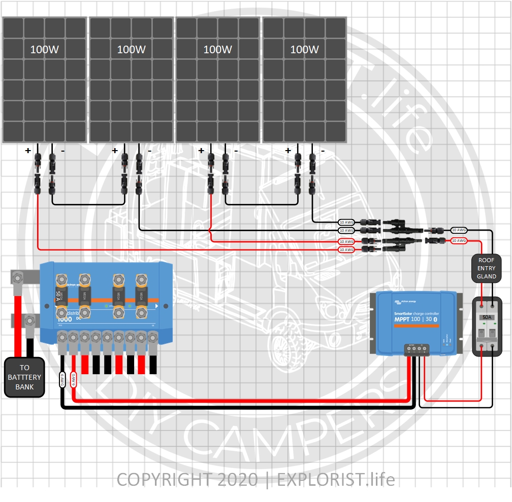
400 Watts – 4x100W Solar Panels – 12V Battery Bank (Click to Expand)
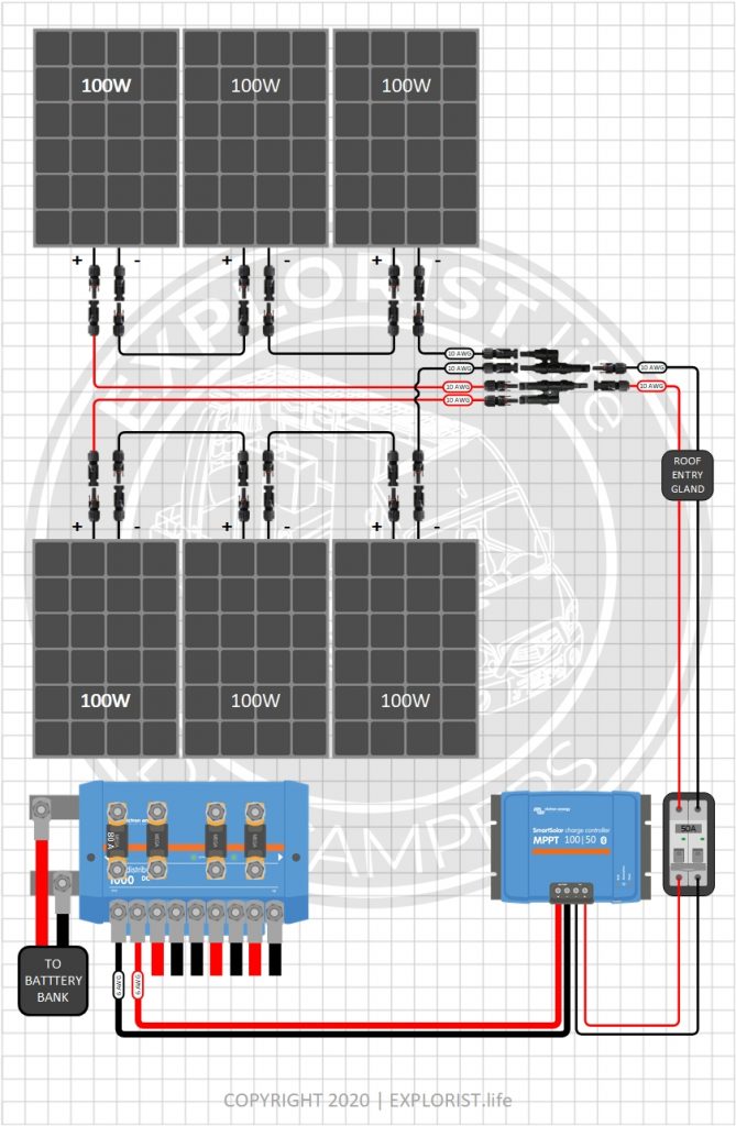
600 Watts – 6x100W Solar Panels- 12V Battery Bank (Click to Expand)
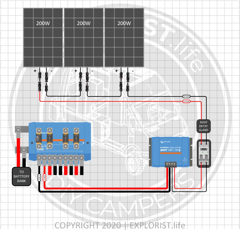
600 Watts – 3x200W Solar Panels- 12V Battery Bank (Click to Expand)
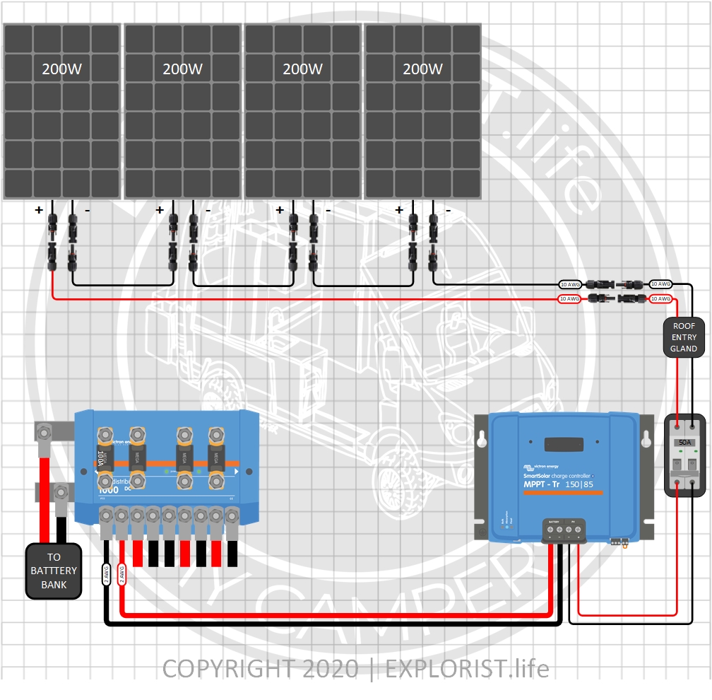
800 Watts – 4x200W Solar Panels- 12V Battery Bank (Click to Expand)
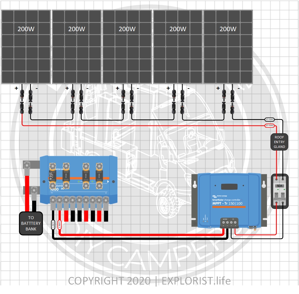
1000 Watts – 5x200W Solar Panels- 12V Battery Bank (Click to Expand)
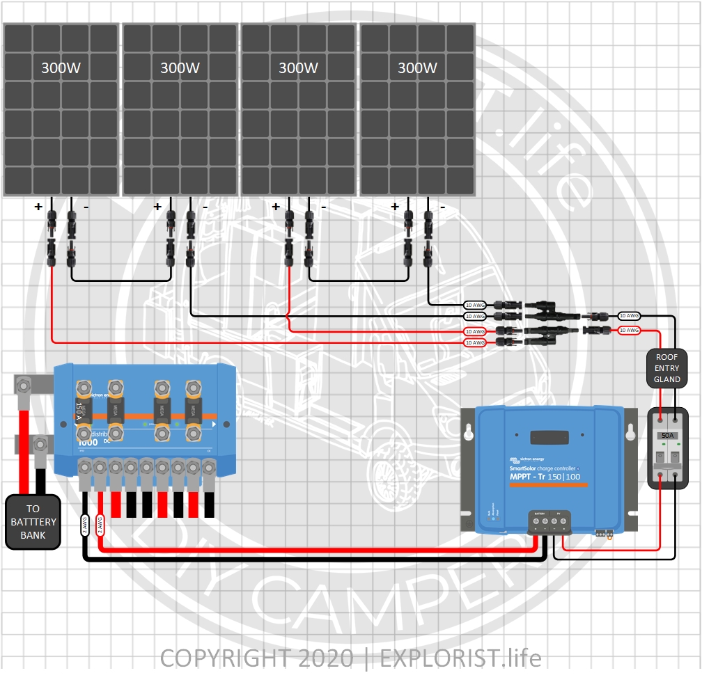
1200 Watts – 4x300W Solar Panels- 12V Battery Bank (Click to Expand)
Order of Operations for DIY Camper Solar Install
This list is a rough guideline of what order things need to be connected for systems using this wiring diagram. THERE IS MORE TO KNOW about this process, though, in the user manual for each component. READ THE USER MANUAL FOR EACH COMPONENT as this ‘order of operations’ does NOT supersede anything in the user manual.
- Arrange all parts & components where they will be mounted
- Mount & secure all components to the wall/enclosure as necessary (EXCEPT Lynx Distributor)
- Wire battery bank together
- Assemble Lynx Distributor, master disconnect switch & shunt assembly
- Mount Lynx Distributor to wall/enclosure
- Verify Main switch is in the “OFF” position
- Wire Positive wire from Lynx Distributor to Main fuse
- Wire Positive Wire from Main fuse to Battery Bank
- Wire Negative Wire from Shunt to Battery Bank
- Connect negative wires from Lynx Distributor to Inverter/Charger, Charge Controller & 12V Fuse Block
- Install fuses inside of Lynx Distributor
- Connect Positive Wires from Lynx Distributor to Inverter/Charger, Charge Controller & 12V Fuse Block
- Connect Positive Wire from Lynx Distributor to B1 Terminal on Shunt
- Verify dual-pole disconnect switch for solar array is ‘off’
- Connect Charge Controller to Dual Pole Solar Disconnect
- Connect wires going to solar array to dual pole disconnect
- Cover Solar Panels with Cardboard
- Connect solar array together (Order does not particularly matter)
- Remove Cardboard from Solar Panels
- Verify proper solar array voltage at dual pole solar disconnect
- Remove ‘wire bridge’ on Victron Orion DC DC Charger
- Connect positive & negative wire from Orion to Starting Battery pos & neg (as per user manual)
- Adjust Orion Output Voltage Setting as appropriate in Victron Connect app
- Connect 10/3 wire from shore power inlet to Inverter/Charger
- Connect 6/3 wire from Inverter/Charger to AC Breaker Box
- Verify all 120V breakers in breaker box are ‘off’.
- Connect AC Branch Circuits to AC Breaker Box if not already connected
- Connect DC Branch Circuits to 12V Fuse Block if not already connected
- Connect RJ-11 cable & BMV-712 Monitor Gauge to Shunt
- Verify proper voltage between main fuse & shunt (Approximately 12V-14V)
- TRIPLE CHECK THAT ALL WIRES ARE CONNECTED, POS (+) TO POS (+) & NEG (-) TO NEG (-) (except series wired solar panels) AND CONNECTED TO THEIR PROPER PLACES IN THE COMPONENTS AS PER THEIR USER MANUAL
- Turn on Master Disconnect Switch
- Turn on Dual Pole Solar Disconnect
- Replace wire bridge in Orion
- Turn Inverter/Charger ‘On’.
- Turn on Main AC Breaker in Breaker box & Branch Circuit breakers
- Configure system charging through the parameters as per user manual of each component

396 Responses
Hi 🙂 what do you think?
I have a 3000W Inverter and 775W Solar, 400Ah 12V (2×200) Batteries. I am using bus bars in my system (MPPT connected to bus bar, battery connected to bus bar, inverter connected to bus bar, etc.). How large does the bus bar need to be to handle 3000W of continuous flow? also my negative bus bar is “quite far” from my inverter so I have a 1m long cable. Do you think I should try to get the negative bus bar closer to the inverter? The cable thickness should be fine but I still might be waisting energy? Or should I connect the inverter directly to the battery? (if yes, should I get rid of the bus bars and connect everything directly to the batteries). Do I need an extra fuse/breaker going to the inverter from bus bar / battery? Thanks for your help 🙂
The blog post you commented on answers all of those questions. It shows wire sizes, busbar sizes, all of it.
Nate,
We have a MultiPlus 3000 Inverter. It worked great for the past year and suddenly stopped turning after a cold spell in Oregon. We have 12v working but no 120v. We have checked the manual and fuses. We are connected to a Lynx distributor. All items were purchased through your store. We also turned it off and waited 4 seconds (as recommended by the manual) and still dead. Any suggestions?
Peter
You’ll want to reach out to whomever you purchased the unit from (Battle Born, perhaps?) for tech support on that. I would say to submit a tech support ticket for orders placed through shop.explorist.life, but I also know that we didn’t sell Inverters in our store last year and were pushing those sales over to Battle Born.
Hi Nate. I have installed the 600w (3×200) version of this system in my van, using 3 x 200w panels from Rich Solar wired in series. All components were purchased from either Explorist.life, BattleBorn, or Rich Solar. I have been living in the van full time for a few months now, and everything seems to be working great, with one exception. No matter the conditions, I can’t seem to get over 400w from the solar panels. The voltage is regularly over 60v, which leads me to believe that all of the panels are working, but I can’t get over 400w because of low amperage. Is this common, or does it sound like maybe a setting in the solar controller, or maybe damaged or incorrectly installed equipment? Thanks!
If you are in N. America… that seems normal for winter. In winter, the sun is a lot further south all of the time and we won’t get as much solar power.
Nate ,I am designing my system per the 50 amp OEM retrofit diagram with the multiplus2.I am getting conflicting info about how it handles portable generator input.It is a Honda 2000 that I plan to use.It sounds like I would have to adjust current input via the app every time I hook it up.The gen only puts out 13 amps.Is there a way around this?Thanks for all the info on your site!
You have to tell the Multiplus how much shore power is available. There is no way for the unit to ‘sense’ this. If following my diagram, though, doing that takes about 20 seconds through the VictronConnect app, so it’s not a big deal.
Hello Nate,
Thank you for your amazing videos and detailed resources for DIY camper builders! I found you through Andy Rawls youtube channel.
We have just turned the corner with our 1978 31′ Airstream renovation, where a complete demo is over and started to build her back from frame up. We will have room for 1100-1200W of solar on top, in a mix of up to eight 100W and two 200W Renogy semi-flexible panels.
Your wiring kit (minus solar) looks just right, but since we are mixing panel sizes, do we need to piece the solar wiring kit up from scratch? I was thinking of ordering the 1200w wiring kit for twelve 100w panels, and have an extra set of connectors for backup. Would that work?
You’re on the right track, but you’ll want to divide the solar panels into two separate arrays. Combining the 100w and 200w panels into the same array is going to give less-than–desired results.
Hi, I have installed this system using all the parts you recommend, and it works great. However, someone who has been doing electrical builds for a while told me that the master disconnect switch (300A continuous) is too small. Since I only have 3000 watt inverter / 12 V = 250 amps, that’s the most I could pull continuous, so I’m sure I’m good on that end.
My question:
I have a 400AH battery bank. If that short circuits, how many amps would go through the switch? That is what I’m not sure of. Thank you.
You don’t size a switch/wires on a short circuit event. 4x lithium batteries may flow well over 1,000 amps during a short circuit event with large wire, which would blow the fuse in this system.
The master disconnect switch is adequately sized for exactly the reason you mentioned.
Hey Nate, this page contains pretty much the exact install I’ll be working on soon (except I’ll be using a BIM for the alternator charging and buss bars instead on Lynx distributor). Anyway, I saw on your links for materials that the heavy gauge (4/0) cable is from BatteryCablesUSA and the #6 is on Amazon sold by TemCo. The reason I bring this up is 25′ of the 4/0 ends up being about $100 cheaper w/ Temco (but I figure it’s for a reason). I just wanted to make sure that I should be buying the more expensive cable (it probably has better copper (OFC copper) and better insulation). Please let me know if that is why.
Also, regarding the lengths of the wire runs on the materials list; I’m building an RV from a U-haul box truck. So would the measurements on the materials list be close for what I need? I figured you based your lengths off a sprinter and added a certain percentage as a failsafe for running short. Long post but I just want to be sure before I go buying everything. Thank you for the great info, very informative stuff throughout!
Why not just buy the kit right from our store? Did you see that info on the page? If not… It’s under the DIY Camper Solar Parts – Shopping List header. This will make your project significantly easier. Also… Just use the Lynx Distributor. It’s cheaper and higher quality than busbars and external fuse holders.
Hi! Thank goodness for you and your detail! We foolishly decided we could do this on the road since we won’t be back home until it starts getting cloudy and wanted to test everything out. We are following the 3000w inverter/600ah batteries with 800w solar panels (4×200, series parallel). I can’t find any similar product on the road to the lynx adapters (which I thought would be one of the easier items), nor can I find a crimping tool large enough to handle 4/0 wire lugs. Those two things are holding up our setup. We thought maybe we could do lugs and a short wire instead of the lynx adapters? Not sure. We were going to order from you, but pick up is difficult on the road. Thoughts? Or if y’all can do some trickery with getting it to us, please reach out and let me know. We’re desperate ha ha!
We ship all of our orders through UPS. Most UPS stores will accept a package for a small fee if you address it to them as ‘general delivery C/O {your name}’
hello bro, thank you for all your information you are the best on that , wich is best inverter to use in EU?
so many appliances is 230V
Same one, just the 230V version. Victron Multiplus 3k 12v 230VAC
Hey Nate,
Regarding the Victron Orion DC DC Charger. I purchased the non-isolated version. In this set-up, is it necessary to use the isolated version over the non-isolated version?
My understanding is that if everything (the vehicle battery and Victron set up) shares the vehicle frame as a ground it would work. but I could be way off.
Are there drawbacks or dangers of using the non-isolated version?
Thank you very much!
You could ‘probably’ use the non-isolated version if following this diagram. I spec the Isolated as it works for 100% of use cases.
Nate, regarding my previous question below, I think I answered it myself, please confirm. The amps don’t change: 3000W / 12v = 250a. What changes with number of batteries is the amp-hours of storage so 6 batteries or 4 batteries would still be 250 amps but the 6 batteries would obviously be more amp-hours of storage than 4? So fuse size is still 400a?
Exactly!
Hi Nate! Absolutely loving your entire series on all subjects, especially the electrical, you are a true master craftsman as well as a fantastic teacher and producer of top-notch training materials. I have a quick question: I have the identical system as your 400W solar system but instead of (6) 110 ah Battleborn batteries I have (4) batteries. I notice you are using 400a fuses on your design. If everything else is identical except I have (4) batteries what effect does this have on my fuse size? I assume I need less than 400 a? Thanks in advance! -Craig
The fuse size doesn’t change with the battery capacity given that the load isn’t changing.
Hi Nate, if you can, please clarify the 4x200W solar panel diagram above. You have all four in series, which would have over 200Voc… but you show that attached to a 150v MPPT ? Seems like it would need to be two pairs in series – each pair in parallel, or a higher capacity MPPT?
BTW, tried to subscribe to your ‘community’, but web site wouldn’t let me. If it’s no longer available, might want to consider removing that from your pages?
I love what you’re doing here – many thanks!
Hey Rienk! All of the panels listed in that 4x200w diagram have a Voc of only ~20V, so even in super cold conditions; all 4x of the panels would be well under the max voltage rating of a 150V MPPT.
Okay… for some reason, I thought I saw the diagram having four panels of 24v/200w panels, which would each have a Voc of 45 (180 for four). I’m not an idiot – just not very observant 😉
Hey Nate,
Thanks so much for all this valuable information.
If I build this system out for the 4x300W panels and initially only install 1x300W panel, would I run into any issues other than slower than optimal charging? Would the 150|100 controller be oversized with just one panel, meaning do these controllers have minimums before they push the charge along to the batteries?
If the end goal is 1200w of solar, you could indeed just add one panel for the time being without any other negative consequence other than slower charging. The array voltage just MUST be 5v above the battery bank voltage for the charge controller to start charging and SHOULD be at least 20V higher than the battery bank voltage for optimal operation.
For 4x300w panels; I’d recommend using our Custom Solar Charging Wiring Kit (https://shop.explorist.life/shop/all-products/camper-wiring-kits/solar-charging-wiring-kits/solar-charging-wiring-kit/#add-solar-wire) and add the following for 4x300w:
-40ft of solar wire (or measure using the calculator on that page)
-7 PV connectors
-1x 2-to-1 PV Branch Connector
-2x PV Fuses
-Victron SmartSolar MPPT 150-85
-SmartSolar MPPT 150-85 Wiring Kit
-Solar Array Wiring Kit
That would get you everything you’d need to add 1 or 4x 300w panels to charge a 12v battery bank. Solar panels would be wired in series-parallel.
Hi Nate,
Love your channel, I’ve installed 6 100 watt panels on my RV and and have begun to purchase according to your “6x100W Solar Panels- 12V Battery Bank” parts list and was on the phone with a sales rep at Dragonfly Energy. The one thing that he said was that wiring 3 panels in series then those two parallel would not work right with the MPPT 100 – 50 that you listed. He recommended they instead by wired all in parallel for that charge controller. I’m starting with 2 100ah batteries. Can you speak to that? I want to buy the right stuff.
Also is it useful to you if I reference you when I make the purchase?
6x 100w panels with a Voc of ~20V wired in series parallel (3 panels wired in each series string with the 2x series strings wired in parallel will be perfect for the MPPT 100|50. Check out my 600W solar array wiring kit I have available here: https://shop.explorist.life/shop/all-products/camper-wiring-kits/solar-charging-wiring-kits/600w-solar-charging-wiring-kit-6x-100w-12v-battery-bank/
@Nate Yarbrough,
Awesome thank you! I had already bought t combiners etc so good to know. Math makes sense to me. The only other issue that would be interesting to know is whether I should get the Multiplus compact 2000 or add a battery and go with the Multiplus 3000. (his explanation was that 2 batteries would not be able to power the 3000 so since the price is close maybe adding a battery now would be the best long term plan)
I bought a kit from battleborn that included a 300A ANL Fuse Kit, is that sufficient for this system (600ah batteries, 800w solar, 3000w inverter) or do I need to upgrade to the one in the parts list (heavy duty anl fuse holder, 400A anl fuse)? Am I totally wrong in assuming these are for the same purpose?
Also, thank you for this. I’d be pretty overwhelmed without the resources you’ve put together.
Hi Nate! Do you have a recommendation for a solar panel brand for a system with 800ah batteries? I have a ford transit 250 high roof (not extended) with one maxxair fan on the roof.
Sure! This video talks about that: https://youtu.be/VP4uOsKVD9U
wondering if this system will work well with these panels and if i can add in the cerbo gx? TIA. 320 Watt Monocrystalline Solar Panel
RNG-320DX4-US https://www.renogy.com/320-watt-monocrystalline-solar-panel/?sscid=31k6_xjcst&utm_source=shareasale&utm_medium=affiliate&utm_campaign=1894429
Sure! There are all kinds of arrays/panels that will work in this sytem. Some examples here: https://shop.explorist.life/product-category/all-products/camper-wiring-kits/solar-charging-wiring-kits/
Hey Nate, this is very similar to my setup. However I don’t currently have shore power. What victron product would you recommend for just a charger? Phoenix Smart, Blue Smart? I just want to plug in an extension cord and would like Bluetooth.
I have 400ah LiFePo4
Thanks
Trevor
I recommend using a Victron Multiplus Inverter/Charger. I do not recommend using a standalone charger.
It appears that the solar array is missing a fuse going to the MPPT.
Not all solar arrays need to have a fuse. More info: https://www.youtube.com/watch?v=s1P31hxlD3I
Hello, is a 300A on/off switch linked in the shopping list still appropriate? Had a battery blow on me and someone is suggesting the amps of the switch is too low. Does that sound right? Thanks!
The 300A master disconnect switch is still just fine for this system.
@Nate Yarbrough, Yeah I followed the diagram, but with 400 ah and was planning on upgrading to 600.
That won’t matter. 400ah, 500ah, 600ah… as long as the loads (basically the size of the inverter) aren’t changing the switch doesn’t need to change.
@Nate Yarbrough, currently in contact with the battery seller, thinking it may have been defective.
Hi! We’re looking at buying your complete wiring kit for our van would it work with a 1000ah setup 5 x 200ah batteries?
Yep! Our battery bank wiring kit can connect up to 6x batteries together.
How about 6 x 320 Watt Modules and 1920 Watt?
That’s too big for a single charge controller, so you’ll want to split in half into two arrays. Two arrays, both with 3x 320w panels in each.
Looking at Victron’s wiring diagram (https://www.victronenergy.com/upload/documents/MultiPlus-3KW-120VAC-12VDC-400Ah-Li-VEBus-BMS-generator-MPPT-BMV-CCGX-Orion-Tr-Smarts-Lynx-distributor.pdf), they have a breaker on shorepower input to the Multiplus. Why do you omit that?
There is a breaker in the shore power pedestal. See the 20A, 30A, and 50A breakers in the shore power pedestal box in the top left?
I’m building a 3×100 12 v battery bank, multiplus 3K, 350W solar, and 30A B2B sprinter. After looking at your wiring diagram and wiring calculator I looks like going with 2/0 wire and 330A fuse should be fine. I assume your 4/0 in the wiring diagram is for a larger battery bank and load. The cost difference is large so don’t want to use 4/0 if I don’t need to. Is that correct?
4/0 is required for the Multiplus 3k regardless of battery bank size. The multiplus 3k requires a minimum of 400Ah of battery bank capacity, though per page 8 of the users manual.
I want to purchase the 6×100 12 v battery bank. I see the list of all parts needed but Do I have to order each part from the different company’s? How can i order the entire kit at once? On one order?
You can get ‘most’ of it from the EXPLORIST.life store at shop.explorist.life. Check out the kits: https://shop.explorist.life/product-category/all-products/camper-wiring-kits/
Hello Nate. What would be the possible implications to the battery bank, if any, if I were to have more than 1 component of the system actively charging at any one time. For example, alternator charging, shore power connection, and solar panel input all actively charging the system.
The individual components in this system will regulate back and/or shut down automatically. There’s nothing to ‘do’ to make this work; it just happens.
Hey Nate, this is some great stuff! Thanks for putting this out there!
I’m in the planning stages of a camper trailer build right now and I’ve been looking at my options for heating and cooling. I really like the Fujitsu 09LZAS1 mini-split because of its super-high efficiency which would let me run heat/AC off batteries for extended periods with no problem. The only problem though is that it says “Voltage/Frequency/Phase 208-230/60/1”. I’d still like 120v AC as well as this heat-pump, so can I just add a 220v(or 230? or 210? not sure which is best or if it even matters) inverter to the lynx distributor in this diagram and wire the mini-split to that? I’m not planning on having alternator charging so I would have an extra slot open. Also do you know any reliable brands for a 220v 60hz single-phase 12v inverter? They seem to be a bit rare and the ones I can find don’t inspire confidence as to their quality.
Any advice would be much appreciated!
At first glance, that should just be a pretty standard 120V/240V Split Phase air conditioner which could, unless there is something I’m missing (keeping in mind I only spent about 20 seconds looking at the unit), should be able to be powered by this system: https://www.explorist.life/24v-6000w-120v-240v-split-phase-camper-solar-wiring-diagram/
@Nate Yarbrough,
Hi Nate, thanks for the quick reply! Looks like just what I need!
My only question about that is that the product brochure specifies the phase for the heat-pump as single phase. Will a split phase 240v power source work with an appliance that specifies single phase? They would both produce the same power, right? Is there any difference as to how appliances run on them? I’m still trying to wrap my head around phases but as far as I understand it split phase and single phase should function identically, right?
Again, your advice is much appreciated!
So… Split phase is the same thing that is in your house given you live in N. America. It’s two legs of 120V single phase that are 180 degrees ‘out of phase’ (making it ‘split phase’). If that air conditioner is set up to run on the standard N. American power grid, it should be good to go given a system capable of delivering split phase (like this one: https://www.explorist.life/24v-6000w-120v-240v-split-phase-camper-solar-wiring-diagram/)
Hi Nate, I just stumbled onto your website and I have to say I am impressed and delighted.
I just bought a component kit from Battleborn Batteries and they sold me a battery isolation manager instead of the Orion DC-DC charger. They say that the BIM is recommended for battery banks with more than 1 or 2 batteries. I am planning on 5 100Ah batteries and I’m not sure what the differences are between the two products.
Should I get the Orion or am I good to go with the BIM?
I prefer use of the Orion. It’s simpler and delivers a more consistent charge. Here’s a blog post over that: https://www.explorist.life/how-to-charge-diy-camper-van-batteries-with-vehicle-alternator/
Hey Nate!
So I’ve been slowly buying everything off your previous 3000w inverter cheat sheet, and just noticed you updated it.
Think you can let me know what has changed between the two? Don’t wanna buy an obsolete part or buy something twice!
Thanks 🙂
For the most part, everything that was changed, was changed in favor of things that were actually in stock and the wiring diagrams were just given more detail. You should be fine.
Hi Nate;
The bus bar to chassis ground in the schematic is a 4/0 cable. I have an 8-11 Northern Lite fiberglass shell camper and the options to ground the system are limited. Northern Lite grounds at the driver side forward hold down with an 8 AWG wire. I can run a 4/0 cable from the inverter to a ground bus bar and attach both the 4/0 cable and the 8 AWG wire to it however am I gaining anything by doing this? I will still have about two feet of 8 AWG wire in the chassis ground line. Any thoughts on how to make the connection? Thanks.
The 4/0 should run all the way to the chassis ground; however you can make that work.
Hi Nate;
The diagram lists a 4/0 cable between the batteries and from the batteries to the inverter. Is 4/0 necessary? That is a large diameter cable. Currently I have 370 watts of solar, 300aH of lithium batteries, and the Victron 3000w inverter charger.
Can I get by with 2/0, which is easier to work with?
Thanks, Barry
4/0 is required as per pg 8 of the Victron Multiplus 3k 12V user manual. I wish that we could use smaller wire too. It’d definitely be easier if we could connect all of this up with 18AWG and call it a day. lol I promise, I’m not oversizing the wire just for shits and giggles.
@Nate Yarbrough, I just looked at pg8 it says 50mm2, isn’t that 2/0 awg? Did I get that wrong?
It says 2x 50mm2. So you could use 2x positive 2/0 wires and 2x negative 2/0 wires, or you could use 100mm2 worth of wire which, rounded up to the next nearest wire size, is 4/0.
Hi Nate, I have four 365W Rec Alpha brand Panels with an open circuit voltage of 44.3v and a short circuit current of 10.26A each. Wiring in series / parallel would give me a solar array at 88.6v and 20.5A.
1. Will my Victron 150/100 be able to handle this solar array? It seems my array is 10W over Victron’s recommended wattage for a 12v system.
2. Will your 1200W solar wiring diagram work with my solar array as far as wire gauge and breaker size goes?
3. My panels are labeled with a max series fuse of 25A, am I correct in saying the series strings do not need to be fused as the 20.5A produced by the array is less than 25A?
Thanks in advance! (for your help and your videos!)
1: That’s not a problem. If there any overages on wattage or output amps, the charge controller will simply limit the output to 100A.
2: Yes. This should also be a good resource (omitting one panel per series string): https://shop.explorist.life/shop/all-products/camper-wiring-kits/solar-charging-wiring-kits/1440w-solar-charging-wiring-kit-6x-240w-12v-battery-bank/
3: That’s correct, yes.
Hi Nate, I want to buy the printable wiring diagram for this, but your link goes to one with 600-1450 watts of solar rather than the 400 to 1200 watts listed at the top of this page. We have only 400 watts of solar panels. Will that one that you linked to work for us?
This system is indeed good for 400w of solar. There are hundreds of various solar combinations available for this system with a change of the charge controller. I actually updated the high-resolution diagram yesterday to include the 400W array from this video: https://youtu.be/01F4QDVJUq0
Hi Nate,
Gidday from the land down under. Thanks sooo much for sharing your extensive knowledge in such a clear format!!! No wonder you yanks are 20 years ahead of us.
I have a battery bank comprised of 4x 12V 260ah AGM’s, which I will wire in parallel (as a temp. back-up for my tiny house grid-feed solar system). I’m in the process of designing my own campervan to do the “Big Lap”, and I just got the 2nd hand batteries free from a friend. I intend to build a similar system to your 12/3000 diagram, just starting with the Victron inverter/ charger as a temporary ‘cabin’ UPS (only for my desktop and a small aircon. unit).
1). Is it necessary to arrange the wires to spread the load/ charge evenly from the centre batteries (as shown on youtube by some of your competitors)?
2). Do all the terminal wires ideally need to be exactly the same length (to charge the batteries equally)? What if I can’t locate the huge 4x 78kg batteries in the same location in my campervan???
3). The Victron manual for the inverter/ charger specifies “2x 50mm gauge wire” for the Australian 240V A/C 12/3000 model (for short lengths). Note that your recommended 4/0 AWG is 100mm2 metric equivalent. The manufacturer clarifies that the ‘2x’ implies “2x pos. and 2x neg. wires”. How is this achieved, especially with single installation holes in the base of the unit???
4). The Victron manual for the inverter/ charger also shows a very simple wiring diagram which indicates a neg. ground between the battery and the unit (you haven’t). Does this apply to my 240V solar grid-feed situation (we have ‘triple’ A/C wires)?
5). Can you recommend a simple substitute for the fuse board that will provide me with at least two temporary 10A A/C outlets instead? I was going to use a 10A 4x plug surge protector, but my desktop requires 2x 10A GPO’s. No doubt the aircon 10A GPO is on the same circuit as well. Or, are breakers a necessary evil and I should just temporarily install your A/C DC fuse board for future use in the campervan?
Appreciate your expert advice. Keep up the great work!!!
1: Wiring the battery bank like I’ve shown in my diagram is the way I recommend. There are 3 other ‘victron approved’ ways, but the way I’ve got on this diagram is the one I find the hardest to mess up.
2: They really do. Every effort should be made to make them the same length.
3: The holes below the pos and neg terminals in the multiplus are pretty large. Definitely large enough to fit 2x pos and 2x neg wires side by side.
4: My design has the ground going from the batteries to the lynx distributor to the Multiplus. In a stationary application, I believe the Lynx Distributor would be connected to your earth grounding rod, but I can’t say for certain as that’s not really my specialty.
5: Breakers are a requirement. You all in Australia have MCB’s in a din rail box though, which from my extremely limited experience, you can get a 5 position (or so) box. That’s probably what I’d go with. (or maybe that’s totally off-base and not at all what is common there. lol)
If I use 800ah of batteries, how will it change what parts/equipment I need to purchase?
A few extra wire lugs, heat shrink, and a bit more battery to battery wire, but that’s all.
Hello again maybe I should have mentioned that this is my first time out great carpenter but not the best on electronics which would you recommend for a 25ft bus with not to many gadgets water pump TV and maybe ac/heat thanks for your help greatly appreciated God bless brother.
You’ll want to start out with a power audit to see how much power your system includes ‘not too many gadgets’ in addition to ‘ac/heat’ will use. Here’s a tutorial: https://www.youtube.com/watch?v=a406IxiU-Xg&t=1s
What size solar system would I need for a 25 foot skoolie conversion and how many batteries do they have to be lithium
You’ll want to do a power audit to figure that out. Here’s a tutorial: https://www.youtube.com/watch?v=a406IxiU-Xg
I see that you’re using a 50 amp fuse between the Orion and the batteries. My alternator can push out 200 amps, and I’m using a Cyrix-Li-Ct to connect my 12v lead acid bus batteries to my four 12v lithium tiny house batteries. What size wire and fuse should I use should I use between the two battery banks?
Thanks,
Adam
This should help: https://www.explorist.life/wire-sizing-calculator/
Why are you using a 150 amp fuse between the 100 amp charge controller and the batteries? I thought the fuse size should be not bigger than 125% the load size, or is it 150%?
That’s a manufacturer’s recommendation.
Why do you use a Master Disconnect that is rated for 300 amps while the main fuse from the battery to the distributor is 400 amp? If there were a load that exceeded 300 amps then wouldn’t the Master Disconnect melt before the fuse blew? Shouldn’t the Master Disconnect be rated higher than the fuse, in the same way that the 4/0 wire is rated for higher than 400 amps?
Thanks, these wiring diagrams are great, as well as all your videos. This has helped me immensely.
-Adam
There will be no loads in this system that will cumulatively exceed 300A continuously; so a 300A switch is just fine. I explain that a bit more at about the 14:30 mark of this video: https://youtu.be/01F4QDVJUq0?t=869
Hi Nate –
The 3000w inverter diagram shows 2awg from charge controller to Lynx Distributer but the list shows 6awg. Maybe I’m reading it incorrectly?
The 2awg vs 6awg will change depending on the charge controller used. 100/50 and 100/30 gets 6 AWG while 150/xx and 250xx gets 2AWG. If you are using one of the smaller charge controllers, just substitute (pencil in) the appropriate wire and fuse size from the parts list into the diagram.
Hi Nate,
Is there a danger in doing series-parallel wiring of 5 panels? 3 in series-parallel to 2 in series, each individual panel the same type (Rich 160w CIGS; 18.9v 8.4a).
Would the differing voltages just average out?
You will have some pretty significant power loss. Here’s why: https://www.explorist.life/using-mismatched-solar-panel-sizes/
Hi Nate, looking to use the “3000W INVERTER | 400-600AH | 400 TO 1200W Kit” but with 2 x 270ah batteries. Does this impact the rest of the system at all?
Nope! Just a few fewer wire lugs and heat shrink from the parts list, but that’s all.
Thank you Nate for your knowledge and resources! This is all so awesome. I am in the early process of researching the electrical system for our tiny house we are building, and after doing the power audit, I think this is the diagram to buy but I have a question (that is maybe a stupid question?). Since we have a dedicated space that can fit more than six batteries, is there any reason I’m not seeing to not have more batteries? I think we may be able to fit up to 8-10. Just wondering your thoughts on power-hoarding!
Not really, but if you are going that route, I’d go with the Battle Born 270Ah batteries. Wiring 10 batteries together just gets a bit cumbersome.
This is soooo helpful! THANK YOU. Sharing.
Nate, one last question! I’m installing two Orion DC-DC chargers (12/12/30) as I have a 570Ah bank. Can I avoid getting two Lynx Distributors by wiring the Orion outputs to a small bus bar that then enters the Lynx Distributor to a 100 Amp mega fuse? (reason being cost & real estate of two Lynx Dist units) Or should I just bite the bullet and get a second Lynx Distributor?
2x Lynx Distributors is definitely the cleanest way to do it. You COULD fuse it externally off of one of the Lynx outputs, but I just really don’t know how much space that would truly save as you’d need an external fuse block of some kind and an additional external junction stud. I would recommend 2x Lynx Distributors.
Hi Nate,
Im looking at your 3000w system. But Im in a 220-240v & metric ecosystem. I will be using the Multiplus II 3000 so how does this affect your wiring diagrams/parts list with respect to AWG, fuse ratings?
Thank you
On the DC side of things, it should be the same. The wiring on the AC side may be different, but I’m not up to speed on what wire sizes are used in a 230V 50hz system.
Hi Nate, I love your videos and blog, all very helpful! I picked up the diagram also. I’m a little confused on a couple of items:
• The above calls for a 60A Mega Fuse between the busbar and DC-DC charger, but the diagram shows a 50A Mega Fuse. Which is correct? It seems a 50A would work if it’s only getting up to 30A from the DC-DC charger.
• I’m using this exact system except I’m using three 190Ah lithium batteries and two of the ‘Victron Orion Smart 12|12 – 30A’ DC-DC chargers in parallel. Any advice on the easiest way to install the DC-DC chargers in parallel? Thank you!
1: It doesn’t matter. Either are fine, so go with whatever is actually in stock.
2: IMO the easiest way to do that is to literally copy/paste the entire DC charging leg of the system. 2x positive and 2x negative 6 AWG wires feeding 2x Orions going into 2x spots on the Lynx Distributor. I think this is the cleanest way to do that.
Hi Nate,
What makes a charger integrated into an inverter (ie: Victron multiplus” relevant if I already have a converter in my solar prepped fifth wheel. does it just over ride the existing converter(charger)? I am very interested in getting the best system for my rig but it seems It would be redundant.
The wiring is simply cleaner when using an inverter charger. You’ve got to introduce sub-panels and transfer switches into the system to make the inverter-only option work effectively in an OEM camper. Plus, most OEM camper converters aren’t capable of charging lithium batteries.
Can you please be more specific what the “wire bridge” on the Orion is exactly? Thank you!
The bridge simply allows the Orion to be ‘on’. If it is removed… you can connect a voltage sensing wire to, say, an ignition source wire or some other type of controller so that the orion turns on in certain scenarios only or with a remote switch or something.
Hey Nate!
I’m trying to figure out which wiring diagram would be the best starting point for the build I’m considering. We have a 50amp 5th wheel and I’m looking at probably 400ah of lithium and 750-1000w of solar.
I want to have a dc to dc alternator charger as well just in case. I’m looking at the Victron Multiplus-II 2x 120 so we don’t need a transfer switch.
Is the 50A-OEM-RV-SOLAR what you’d recommend?
This is the diagram and parts list I have for a 50A OEM RV Retrofit: https://www.explorist.life/50a-camper-inverter-with-solar-alternator-charging-wiring-diagram/
I went ahead and bought your diagram, and got all the products you’ve listed. I’m going to be working on my solar install this week, what I’m wondering is when finished will I have to manually switch from solar to shore power, or do any of these products do that automatically?
I know there are some switches out there that say they do it automatically. Are there any that you would recommend?
It’s taken care of automatically.
Nate!! Awesome info…my whole system follows your instructions to a T…now Im adding B2B charger and you call for a 60A terminal fuse..but only 50A or 80A avail…plz help! Thank you!
Either 50A or 80A will work for the DC DC charger shown. Whichever is available is fine.
Hey Nate,
I’m currently working through all of your resources, which are incredible. I’ve done my power audit and it came out to about 290 amp hours per day. I would like to go ahead and get a 4th battery in the event that I want to upgrade one of my fans to an AC in the future. My roof rack only allows for 2 175W panels and I would also like to have the 3000W inverter since I’ll have an induction cooktop. So with that in mind, now I’m choosing between your 3000W 400-600ah 400-1200w solar wiring diagram and your 2000W inverter, 200-400ah 200-700w solar wiring diagram. Do you have any thoughts on which plan I should use? A mix? Thanks for all the work you’ve put in on all of this.
best,
Matt
The 3000W 400-600Ah one would probably be best for those loads.
Nate,
Great stuff! I’ve been following for quite a while now and appreciate everything you post.
Sometime back I seem to recall you mentioning a 50A transfer switch with a second contactor that could be used for turning the converter on/off. I cannot for the life of me find that reference, nor can I find anything like it from searching. Any chance you can help me out?
Thanks in advance,
–edge
Hmmm… That’s not ringing any bells. What is the context? What would that be used for?
Hi Nate
thanks a lot for all that information, love your blog, was advised to look at your channel by the person who sell me all the Victron stuff (he work for a boat shop in San Diego perhaps you know him).
I would appreciate your advice on the b2b wiring from the pickup truck to the trailer. I have a ton left of Ancor Duplex flat wire AWG 6 size https://www.ancorproducts.com/en/123705 and I was thinking to use it from the truck battery to the trailer.. do you think it could be wise to use it ?
For the Orion shown in this diagram, that would be a great choice.
I don’t see the shunt anywhere in the parts list. Is it perhaps included with the 712 Battery Monitor?
Indeed it is.
Hello – question 🙂
I grabbed a wiring diagram (and they are awesome thank you so much) but it doesnt seem to tell me what gauge wire to use when creating the battery system. As in, I dont know what wire size to use between all of the batteries. Can you help? Sorry if this has been asked before. I have a 600watt AGM bank and a 900watt Lithium bank I am working with. Thanks!
The wires between the batteries would be the same as the wires from the Batteries to the Lynx Distributor. So, 4/0 in this diagram.
@Nate Yarbrough, Excellent. Thank you.. Same goes for both battery bank sizes?
Indeed!
On the “Inverter Charger to AC Distribution” section, a 50amp single-pole Square D HOM breaker doesn’t exist. The maximum is a 30amp. Am I supposed to get a 2-pole 50amp breaker?
The product linked in the parts list listed as “50A Square D HOM AC Breaker” is indeed a 50A single pole square D HOM breaker.
Hi, Nate. I just discovered your blog via your excellent YouTube series on DIY camper electrical systems. Thanks for such sharing your wealth of experience with all of us.
I notice both your site and the Battleborne site describe Victron inverters as “2000 watts” for the MultiPlus Compact 12/2000/80-50, “3000 watts” for the MultiPlus 12/3000/120-50, etc. while Victron describes them as “2000 volt-amps” and “3000 volt-amps”. I have a very general understanding of how reactive AC loads aren’t as simple as volts-times-amps-equals-watts and how a MultiPlus 12/3000/120-50 is actually only rated for 2400, 2200, or 1700 watts at various temperatures.
Does a “3000 volt-amp” Victron inverter actually have less capacity than other manufactures’ “3000 watt” inverters, or is it just that most companies rate inverters using purely resistive loads with unity power factors? Is it a distinction without a difference?
Yeah, Victron inverters are measured in kVa (Kilovolt Ampere). Watts can be caluclated by using Watts = 1000 x Kilovolt-amps x Power Factor. Now… where this gets messy… is that every device and component has a different power factor depending on the ‘type’ or power it uses (resistive, inductive, etc) or general efficiency of the device.
Power factor (PF) is the ratio of working power, measured in kilowatts (kW), to apparent power, measured in kilovolt amperes (kVA). Apparent power, also known as demand, is the measure of the amount of power used to run machinery and equipment during a certain period.
So… It gets messy in a hurry. It just simply less confusing to say that the Muliplus is 3000W, even though it’s a little less in real life because pretty much nothing uses power 100% efficiently with a “1” power factor.
Other manufacturers… I don’t know. I suspect their wattage ratings are also probably kVa ratings. I have asked several popular companies about this and never got a response.
Following up to my previous question and having done more research, induction hob is definitely power hungry, not sure what I’ll go for yet, but if I need more power how hard would it be to wire in a bigger inverter? Victron do a 5000w 12v. Is it virtually the same?
Alternatively, if I found I needed to upgrade in the future, how would it be to upgrade
For 5000W of Inverting power, I would recommend going up to a 24V battery bank. Victron does not make a 5000W 12V inverter.
Hey Nate! Just want to say thank you for all the help thus far, I purchased a few of your diagrams and they’re amazing. One question I had however is the fact my 120v outlets aren’t putting out. The 12v side of the WFCO breaker box is working and doing great. On the 120v side, I have confirmed that the breaker bar is getting the right voltage but the only thing working is the breaker box’s outlet on the back, further confirming the system is getting power. After confirming the right breakers, wire (12/3) and using you 120v diagram and double chewing my work, I have lost all ideas. Before I bring in an electrician, do you have any possible ideas of what could be happening?
If the outlet on the back of the box is working but no other circuits are not working, I highly suspect there is something going on with the wiring of the other circuits, so I’d dive further into troubleshooting the wiring of your additional branch circuits and verify those are correct.
Hi Nate,
Thanks for all the help that you give to all of us out here!
My question is about connecting the charge controller. A prominent online source of RV solar power equipment designed a system for us and provided a schematic. I am now in the preliminary stages of installing everything. The schematic shows the positive terminal from the solar array (using 10 AWG) going through a Midnight Solar -“Baby Box” connected to a 15 amp DC breaker, then continuing on to the Victron 100/50 charge controller. The negative wire is going straight to the charge controller. The schematic then shows the positive wire (6 AWG) coming out of the charge controller, going through a 63 amp DC breaker in the “Baby Box” to the battery bank. The negative is going straight to the battery bank. This is nothing like you show in your installations. Your design seems much more sound, not to mention correct. Can you please comment on the two different approaches to wiring the charge controller into the system? Fuse sizes, placement, fuse type, wire sizes etc. Thank you so much!!!
Ultimately, the way I show in my diagrams is the most correct according to both the NEC and the ABYC that I possibly can get with the parts that are available to the general public. I don’t like to comment on what other installers or retailers do as they may be following a different set of codes or standards than I am.
@Nate Yarbrough,
I understand completely. I now know how I am going to wire my system… Thank you Nate!!!
Hey Nate,
I was speaking with a rep at BattleBorn today and we were talking about this wiring diagram. He said that BattleBorn recommends using 2/0 cable instead of the 4/0 that you have listed. Something about the BB Batteries having an external BMS. Victron recommends the 4/0?
Just curious what your thoughts on this are.
Thanks for the great content!
Since Victron specifically recommends 4/0 wire to power the Multiplus 3k on pg. 10 of the user manual, I cannot recommend anything smaller.
If Battle Born wants to recommend something smaller, that’s fine, and their prerogative because if something goes wrong, it will fall back on them since they are authorized Victron Distributors and would be handling the warranty claim or service. Just get that recommendation in writing if you decide to go that route.
@Nate Yarbrough, Appreciate the advice. Thanks Nate.
Hi Nate. We got our van on May 1st. Done lots of work already. I’m wondering if I need to correct something I’ve done with my Lithium batteries before putting them into the system. I installed my two MaxxAir fans and was running them off a battery for several hours to help get rid of the glue smell (from installing Thinsulate.) As I have three 206Ah SOK batteries, do I need to bring them all up to full charge before connecting them in parallel to the system? If I have to make sure they are fully charged so that they’re balanced, is there an easy way to do that without the system being functional yet?
Thanks much
Calvin
Batteries wired in parallel will self balance, so you should be good to go.
I realize it’s a little out of scope for this diagram, but since it’s a critical component, I was hoping you could shed light on what wires to purchase for wiring DC and AC appliances to the AC/DC distributor box. I found the following marine grade wires, but am trying to determine if I need triplex wire for everything or only duplex wire – or if it depends on whether it’s AC or DC?
The AC/DC distributor box you link to (30amp version) is sold out, would the 50amp version work just as well, even if you only ever plan on doing 30amp?
Wire: https://www.boatid.com/ancor/safety-16-2-awg-1-red-yellow-flat-duplex-cable-mpn-1247-ft.html
Thank you for all your detailed diagrams and videos – they are a gigantic help for confused, yet keen, DIY’ers such as myself!
I have a list of my recommended wiring below the calculator on this page: https://www.explorist.life/wire-sizing-calculator/
Triplex wire will be for AC wiring, duplex for DC branch circuits (usually).
Hey Nate, with the shore power I don’t really plan on being in campgrounds too often. Would it be better to install a regular 110v plug instead? (or stick with what you have and buy an adaptor)
I kind of just want to take an extension cord and cut off the male end, then run that from the inverter to dangle under the van. Think that would be a problem? Would I need any additional parts?
I would recommend wiring is with the parts I have shown on this diagram and parts list and then just carry a 30A to 15A adapter for those times you only have a standard household outlet available: https://amzn.to/2Qxt3iS
Hi, thanks for all of this helpful information. I purchased the high resolution diagram. It shows a 50A circuit breaker between the panels and the charge controller. However, I don’t see it on the parts list. My series-parallel panel setup ends up with a maximum 88 volts, 20.24 amps. My charge controller accepts up to 60 Amps. You have a 50A SquareD panel-type circuit breaker listed here but that does not seem like the correct type. Can you please provide me with a link to purchase the 50A panel in your diagram that can handle 88 volts? Thank you.
That breaker is listed in the solar parts lists at the bottom of the blog posts. Here is a tutorial for how to install it: https://www.explorist.life/how-to-wire-a-solar-disconnect-for-a-diy-camper-electrical-system/
The batteries in the diagram are all parallel?
Indeed. 12V batteries wired in parallel to form a 12V battery bank.
A few questions:
I’m looking to do this system in the U.K., how much do I need to change to adapt this to the U.K. 230v? Would the shore cover the range of 110v to 230v should I take the van to the US for example?
If I wanted to add the victron control center screen, how easy would that be?
Also should there not be a BMS in this system or is that covered in another way?
Finally would this inverter be powerful enough to power an induction cooktop? I want to do all electric so I need to have enough power to cover it all
Changing shore power and the inverter from 120V to 230V should be the only change necessary (and the associated AC wiring).
Adding the Color Control GX would indeed be pretty simple.
These batteries have an internal BMS, so an external BMS is not necessary.
This inverter would likely power your induction cooktop. Verify the wattage of your specific cooktop falls in the specs of the inverter, though.
Hey! Love the info on your site. Do you have a wiring diagram for a pair of Orion TR Smnart B2B chargers installed in parallel available?
I don’t, but you would just attach the 2nd charge controller to an additional spot on the Lynx Distributor (This may mean adding a 2nd Lynx Distributor). Pretty much just copy/pasting the entire alternator charging leg of the system.
If I were to do a 24 v battery config, what about this parts list would change besides the Victron components? Would the fuses still all work?
Pretty much everything would need to change. If you don’t need more than 3000w of Inverting power, I recommend sticking to the 12V battery bank like I recommend here. If you need more than 3000W of inverting power, I would then recommend going to a 24V battery bank. Here is a diagram for that: https://www.explorist.life/24v-6000w-120v-240v-split-phase-camper-solar-wiring-diagram/
Based on my roof configuration I can maximize my available roof space by having 8 100W panels. What configuration of series/parallel would you recommend or would I want to link them all series?
Series-parallel. Depending on the solar panels you plan on using… 4s2p will probably be the best bet.
Nate, I thought I had sent this question but now can’t find it.
I am worried about the fire risk from Li batteries. Is this a valid concern? If we didn’t use Li will everything else on the list work with Lead – Acid?
Tim
Ultimately risk tolerance is a personal decision, but if I felt there was a fire risk with batteries, do you think I would include them in each and every one of the diagrams I have on my site?
@Nate Yarbrough, thanks Nate! When I talk to people about what I am planning some will say “don’t Lithium batteries cause fires?” Didn’t mean to insult you, just needed some confirmation.
Ahh, yeah… People love to talk, that’s for sure. There are issues with batteries catching fire in super-low-end consumer electronics like no-name hoverboards or e-bikes, but to my knowledge, Battle Born has not had a single battery catch fire in-use.
Your Webiste is SO helpful but unless I am getting confused is the wiring back to the battery not rated high enough?? My system really closely matches this diagram. But the 4/0 guage wiring from busbar to the battery only matches the multiplus and not including any load from the 12v. or am I getting myself confused and i shouldn’t be factoring this in. From what I understand the MP can pull upto 400a and 4/0 maxes out at 440a. I welcome your help Nate, please 🙂
The Multiplus 3k can realistically only pull 250A so there is plenty of overhead for the 12V fuse block. (3000W / 12V = 250A)
I think I figured out my answer about the 60A fuse and what gauge wiring to use. When I get the van (which should be soon based on info from Ford) I’ll swap out the stock 60A fuse and put in a 50A fuse; then I’ll use 6 AWG wire as in your diagram. I understand as long as the fuse is protecting the wiring behind it all should be okay.
50 or 60A fuse are both fine for that location.
Hi Nate,
We’re converting a Ford Transit van to a camper. It has a customer connection point in the driver seat pedestal that is already protected by a 60A fuse. I plan to connect the alternator charging circuit to that point. Do I still need to use the 50A fuse shown in your diagram? If I can go with only the 60A fuse, should I switch to 4 AWG wire to run into the DC-DC charger or will the 6 AWG wire be fine? It will be about a 12-14 foot long wire run from the seat pedestal to the Orion charger.
Thanks! (I found answers to my previous questions by continuing to look through other links in your website.)
50 or 60A in that location wouldn’t matter. Don’t use 4 AWG in either situation, though. 6 AWG is the largest wire that will fit into the Victron Orion.
Hi Nate,
In my original plan I was looking at 600W solar so I bought the MPPT100/50 unit, but then decided to dial it back to 400W of solar due to space on the roof. Will the MPPT 100/50 still be fine with only 400W of solar? There is a possibility I may add 200W more in the future.
Thanks,
Calvin
Yep! That’s fine.
Hi Nate,
A question about installing/wiring the Blue Sea systems single circuit on/off switch. On the backside it indicates an input bolt and an output bolt. If it’s just a simple open/closed circuit switch, does it matter if I attach the red (+) wires on the opposite attachments? It’s just that if I follow the input/output indicated on the switch I have to put it in upside down due to the orientation of the battery fuse and Lynx distributor box and how easy/hard it is to connect the 4/0 cables.
Thanks,
Calvin
I emailed Blue Sea a while back and they said it didn’t matter which was input vs output. But ultimately… I guess in this scenario… the input vs output changes depending on if the battery bank is discharging vs charging. lol But no… Install it right-side-up and call it good.
Hello Nate, thanks for your great work for the community! Question: why there is no breaker between shore power and the inverter/charger? The manual for Multiplus requires breaker in the “AC in” line…
There is a breaker in the campground power pedestal or in the breaker box protecting the outlet that the shore power cable is attached to. This satisfies that requirement from the manual.
Nate. Can’t thank you enough for everything you provide to this community. It’s huge. I have a few questions I was hoping you might be able to help with. I’m basing my build off of your 600 Watts – 3x200W Solar Panels design. The one thing is, I was hoping to run the panels(Renogy) in parallel in hopes of avoiding partial shading issues, but I noticed you have these built in series-parallel.
Is this because you advise NOT running in parallel(to a 100/50 mppt)? I think I understand your videos just enough to get that in parallel I’d be adding the amps and thus need to increase my wire gauge. What are your thoughts? Is partial shading less of an issue than I’m making it out to be? Do I not really even have a choice because of the amount of amps I’m pushing through the system? Any insight would be really appreciated.
The solar array voltage needs to be at least 20V higher than the battery bank voltage for the MPPT to properly do it’s job to an optimal level. If maximum solar output is the goal, don’t park in the shade. 🙂 Additional info: https://www.explorist.life/solar-panels-series-vs-parallel/
Hi Nate, Thanks for all of your hard work. I have followed your Hi-res diagram for the 3000W INVERTER | 400-600AH | 400 TO 1200W SOLAR -CAMPER SOLAR KIT. Solar is not hooked up yet but everything else is. With the exception of the Victron BMV Battery Monitor (and shunt). Instead, I hooked up a Simarine Pico Shunt and Battery monitor system. My problem is the Victron 3000w Multiplus inverter will not turn on (charge or inverter). I verified 110v on the AC in side and 13.4v on the DC in coming from the Battle Born 400ah battery bank to the Multiplus. I was kind of under the impression from the installation manual, it should just “turn on”. maybe I am missing something on the controller side of things. Do I absolutely need the Victron BMV to turn it on? Maybe the Multiples is “bad”? I have read on a few forums non functional units do get shipped out. Nothing from Victron yet… Thanks for any help.
If you have 13.4V at the positive and negative DC input terminals of the Multiplus, the unit should indeed turn on. If you think the unit may be faulty, contact the distributor you purchased the Multiplus from (Hopefully this was Battle Born) and the will be able to help you troubleshoot and get it going or replace it if necessary.
Hey! Just starting my skoolie conversion this past month at age 22! I have everything accounted for with your help but a lynx adapter. Has anyone been able to find one anywhere?
They are estimated back in stock early next week.
You always mention the importance of a shunt, but I don’t see one on the shopping list. Is it in there?
The shunt is included in with the Victron BMV-712.
Hi, Love your stuff.
This is kinda the system I had imagined for my Rosa Bus, one early question is, my bus has a 24v system, and I have read that 24v solar setup is kinda better, what would need to change in this layout to make it happen.
The whole 12/24v thing is a bit confusing at this early stage, put 2 x 12v batteries together and you have 24v?
The entire diagram would pretty much need a re-work for 24v. From the components all the way down to the wire lugs & fuses. Too much to really list as a reply here. If it’s just your alternator that is putting out 24V… I would recommend building a 12V system and using a 24v to 12v DC DC converter to charge the 12v battery bank from the 24v alternator.
Nate,
I purchased 16 cells(3.2V 100Ah LiFePO4 solar battery pack iron). It was my thinking that I would make 4 100ah lithium batteries for my solar install. In doing more research I realized that I would need a BMS.
My question for you is, do I need a BMS for each battery that I make? Or, can I make a 16 cell (12 volt) battery and use one BMS?
Also, can I pay you to do a diagram on exactly how I would make each battery and the items need for the batteries? If I am able to make a 16 cell battery can I pay you to do a diagram for that?
Thank you for your consideration in this matter.
That would depend on your battery cell and the BMS you have chosen to use and you would want to reach out to the manufacturer for that information.
If a full-on DIY battery is a bit too advanced, I would recommend buying batteries with a built in BMS like the Battle Born batteries on this page so you don’t have to bother with the BMS issue.
Nate,
The current converter and fuse and wiring is under my bed. Can I put Lithium batteries and the other components for the system in the compartment under the bed?
Yes.
@Nate Yarbrough,
Thank you. I have studied a lot of how to and such and your site and explanations are by the easiest to understand. Thanks for your hard work and dedication to help the lame understand how the install a Solar System on their camper.
Thanks
Chuck Pierce
The Black and Gold Bandit
Will this work with 12 Nissan Leaf batteries?
I don’t know enough about those to say for sure.
Hi Nate! Awesome website, I’ve spent hours here today!
I have a few questions that I can’t seem to find the answers to online. I’m very new to this so bear with me, I’ll try to explain it all correctly. I’m a bit long-winded, sorry in advance.
We went with 3000w inverter, 600w solar panels, and a battery bank totaling 600 amp hours. We’re planning on having our outlets be 110 AC, and our lights on 12v DC.
1. The inverter that we bought is the 3,000w inverter (NOT inverter/charger) from renogy. Is there a way for us to still use shore power directly to our system without that? Meaning is there a way to bypass charging the batteries entirely and connect shore directly to the system while we’re parked somewhere with electricity? (we have an external charger for car batteries we could use if need be).
2. DC and AC systems must be kept separate, correct? We cannot run both AC and DC on the same circuits? And we must have different breakers for each?
3. The Victron Smart battery monitor that you listed on this page is expensive, and I’m wondering if it’s necessary or just an added perk to monitor your batteries if you want to?
4. To keep things streamlined and cheap, we’d like to add in the shore power and alternator connections later. Will the rest of the system still function if we leave that out?
5. Do you have to use different types of wires for DC and AC circuits? I saw in another blog post of yours that campers and boats must use stranded wire, but most DC wires I’ve seen running to lights and stuff is 18awg, which is only two strands instead of three. Are we able to use 14awg stranded wire instead of 18, if so what do we do with that third ground wire?
Thanks for reading all that! I’d really appreciate any help you can give!
1: The most straightforward way would be to use a transfer switch with the 2 inputs being shore and inverter with the output going to the breaker box. You would just need to turn your charger off every time you disconnected to shore power.
2: Correct. They are completely different. If you tried to combine them, somehow, you would be running 120V on a 12V system, which would fry every single piece of 12V equipment you have installed (batteries, inverter, charger, etc.
3: The battery monitor is how you tell how much power you are using from your batteries and how much power is left (and a lot of other data). Althogh the system will function without it, I feel this is a necessary component as leaving it out would be like driving your car without a fuel gauge or speedometer. A less expensive option to the Victron BMV-712 is the Victron SmartShunt: https://amzn.to/38LchTs It is wired in the same way I show in this diagram but lacks the physical gauge and is monitored via bluetooth from your phone.
4: Yes. Plan for it now, though, and leave ample space on your busbars for those components down the road.
5: 120V uses Triplex wire: https://amzn.to/3bIcOre 12V wire uses Duplex wire: https://amzn.to/2LE2NAG (using appropriate sizes, of course)
Hey Nate,
Going through everything and getting ready to order all of my components! Thank you so much for doing this, I would not be able to do this without your help! I was able to sub for some of the products on the list, but the hardest one to find was the Blue Sea ANL Fuse block. The only option on Amazon was from a 3rd party seller who was charging a ton for shipping and didn’t have great reviews. This is another one that I found that looked similar, will this work in it’s place?
https://www.amazon.com/gp/product/B01B28RSWQ/ref=ewc_pr_img_20?smid=A3QWSZ44N8P3XH&psc=1
Thanks so much!
I cannot recommend anything other than Blue Sea ANL Fuse holders at this time. Looks like they are out of stock on amazon at the time of writing this comment. A quick google search for the same ANL Fuse should turn up alternative sellers outside of Amazon.
I have been reading about the Victron components and I was wondering about the BatteryProtect devise. You don’t use one in your electrical layouts and I haven’t seen them used by anyone else sharing their schematics. Are they not useful?
It’s a great device, but not a necessity. I only include components into my diagrams that I feel are a 100% necessity to build a high-performing system. If you wanted to use a battery protect, it would go between the Lynx Distributor and the 12V fuse Block in the power distribution panel.
Ugh, *device.
I’m working through the parts list with the wiring diagram. I’ve only made it through the battery assembly and on to the busbars and already I think the list is missing two 4/0x5/16″ lugs for battery connections (I count 22 but only 20 in the list) and there is no shunt listed in the components. I am far from an electrical expert so appreciate any guidance.
The shunt is included in the Victron BMV-712 battery monitor kit. I’m pretty sure my lug counts are accurate but feel free to buy as many lugs as you feel necessary.
@Nate Yarbrough, Thanks, I do tend to get a bit mired down in the details. I spent yesterday feasting on your blogs and videos (which are invaluable!) so I’ll try to manage my stream-of-consciousness questions.
Hi. Really glad I found your site and diagrams. Planning on doing the alternator, solar, and shore power charging options. Got three 200Ah 12v lithium batteries coming. Van has dual 250amp alternators. Can only comfortably fit three 160W solar panels on the roof rack. My question is regarding the shore power inlet. I’ve read about people using standard 3 prong inlet and extension cord so they don’t have to manage the heavy cable. Do I have to use the 30amp type plug for exterior shore power or can I use a stand three prong inlet in this set up? Thanks a ton!
I mean, you COULD use an extension cord with a 15A inlet, but it would handicap the system if you did that as this system is designed to handle 30A shore power passthrough. This is a high performing system. Maybe limiting the shore power input capacity isn’t a good spot to cut corners?
Forgot to mention planning on running the panels in series parallel.
Hello, so much great info on your site. I am using your 400-1200 watt solar kit set up. I just bought 4 175 watt solar panels and am using a 150/70 mppt controller. I already bought the 150 mega amp fuse, will this still be ok with my set up or should I purchase a smaller fuse? It looks like everything else on the diagram is still the same. I appreciate your help on this.
The 150A fuse will be just fine paired with 2 AWG wire.
Would it be possible to remove one of the solar panels from the 1200 watt configuration and end up with a 900 watt setup?
Yep! 🙂
Is the 2 awg wire and lugs missed from the list here. I purchased the diagram which illustrated 2awg wire. But this list does not contain them.
Check the bottom of the blog post for various solar setups that will contain 2 AWG wire if necessary.
What about a BMS? I thought it is needed for lithium ion batteries?
Battle Born Batteries (The ones featured in this diagram) have an Internal BMS, so it’s not something we need to mess with.
Nate, you came off of the positive end of battery chain on the left of diagram (call it battery one). You came off of the negative battery chain on the right (call it battery six). Is there logic to this? Or does it matter where you tap the chain?
Your diagrams are great.
Michael
Yep. The way I’ve shown in the diagram is intentional and very important. This makes sure that power is pulled from the entire battery bank evenly as opposed to only one end of the battery bank.
This information is super helpful! Thanks for making a complicated subject so user friendly.
Glad it helped! 🙂
Hi Nate, Thanks for all you do you have been an incredible resource for all of us and deserve tremendous credit! I noticed the parts list for the “Master Disconnect” links to Blue Sea Systems 300 Amp m-Series Battery Switch Cat. No. 6010, which is a Dual Circuit switch. It seems to me that this has more capability than the single disconnect would warrant. Wouldn’t the Blue Sea Systems 300 Amp m-Series Battery Switch Cat. No. 6006 be the one to choose? Same ratings but with only single circuit disconnect capability? Thanks!
Thanks for the heaads up! Link has been fixed.
I ended up with 2-200 watt rich solar panels and 2 100 watt rich solar panels and was curious to know of any compatibility issues wiring in series with the victron 100/50 (recommended by battle born) in the 3000w/600watt solar/400ah sytem.
thank you
Bobby J
Yep! Here’s how mixed sizes of solar panels work together: https://www.explorist.life/using-mismatched-solar-panel-sizes/
TY TY TY You are the man! I have a question. I read all the comments below and did not find a match.
I have a 48V system: Victron MPPT-150/45 (3 -420W panels ins series), Quattro- 48|5000|70-100 120V, Orion Tr-48/12, and the lynx distributor. I am converting 48V to 12V and 48V to 24V. I am limited to just 4 connections on the Lynx but need 5 (MPPT, Orion, Quattro, 48-12, 48-24). So, I was wondering (since the mppt and quattro are 12 inch away from each other) can I connect the mppt to the quattro directly? Sort of using the quattro as a mini bus bar. OR can I duble up on the lynx in any way? For example the two converters 48/12-24.
If so should I do a + inline fuse
I would recommend getting a 2nd Lynx Distributor. Lynx Distributors are made to be bolted together, end to end, for additional fused connections.
@Nate Yarbrough, I agree and did have one, but I do not have the room for it.
Hey Nate,
I was about to order six of the 100Ah Battle Borns for this set up in my van, but then I stumbled across the RELiON 300Ah bats. They’re a bit pricier, but obviously a massive space saver with x2 300Ah batteries vs x6 100Ah batteries.
https://relionbattery.com/products/lithium/rb300
The specs look virtually identical to my untrained eye. The only difference I see is that it says the RELiON is 12.8v. Would that .8 vibe with this system or would I need to make alterations? I’m guessing that 12v batteries in general aren’t exactly 12v on the dot, so maybe this is a silly question.
Any advice would be greatly appreciated. Thanks for amazing library of information!
This diagram is compatible with those batteries.
@Nate Yarbrough, Thanks, Nate!
Hi Nate,
Recently purchased Victron Package of solar components. 800 watts of solar panels, Victron 24/3000 Multiplex 70/50, running 24 volts, Orion 24/12 step downs, Victron Smart Solar MPPT 100/50 solar controller,and the new Cerbo GX monitoring.
Do you have any wiring diagrams for this? I’m doing stepdowns due to 12 volt appliances and need to power the 120 circuits.
I have most of the components/tools for wiring but I don’t want to make any mistakes.
Other components include: Midnight Solar Baby Box and Breakers, Mega Fuses, Lynx Distributor 1000A DC distribution and Lynx 1000A shunt. If there is a cost involved, please let me know. Thanks much….
Vern Allen
At this time, I do not have any diagrams for 24V battery banks. Sorry about that!
Hi Nate,
What about BIM for this diagram? I’m getting a duel alternator installed.
The BIM would work as well. You’d just need bigger wires & fuses for the alternator charging leg from the Lynx Distributor.
Nate, great drawings. I am building 1000w solar, 600ah battery almost idenditcal in layout and parts as the 3000w inverter/400-600ah battery/400-1200w solar. I bought all parts using your links (hope it helps). I have a second alternator installed on my Sprinter Van. It is 280w alternator with and external regulator Balmar MC614 programmed for Lithium batteries. Can I connect this alt straight to the lynx distributor or do I still need the Orion TR Smart DC/DC charger?
Thanks,
Michael
At the current time, I know very little about that particular alternator setup. You could always dive into the manufacturers recommendations and see how it would play if connected directly; or you could use the Orion to make 100% sure. This will take some due diligence on your end.
Nate,
On the “INVERTER CHARGER TO AC DISTRIBUTION” part list section you list a 50 amp breaker between the inverter/charger and distribution panel. However, in the https://www.explorist.life/how-to-wire-a-power-distribution-panel/ section and YouTube Videos you mention a 30 amp breaker. I’m assuming the 50 amp breaker is the current update?
Correct.
Hello Nate,
Great site and very helpful!
1) Rather than the victron DC to DC 30 amp charger I would like to use the Sterling 12 volt and up to 60 amp charger. https://www.sterling-power-usa.com/SterlingPower12volt-12volt-60ampbatterytobatterycharger.aspx
2) Rather than to 6 battle born batteries I would prefer to go with 2 Lithionics GTX12V315A-E2107-CS200 for a total of 630 Amp Hours instead of 600 with Battle Born. https://lithionicsbattery.com/product/12v-315ah-e2107-gtx-battery/
Do you see any big issues with these changes in your 3000W INVERTER | 400-600AH | 400 TO 1200W SOLAR -CAMPER SOLAR KIT? If you would need to consult on this just give me an estimate.
Thanks for your help!
Jeff
If you are using all Victron components for the other items… I recommend the Victron unit over the Sterling so that all of the components can ‘talk’ to each other for temperatures, voltages and such. Also… Victron is working on a firmware update so that solar and alternator can synchronize charging and charge from both sources at the same time. You will NEVER have that capability with the Sterlilng unit.
If you decide to go with the Sterling; be sure to change the wire & fuse sizes as appropriate for the increased charging load.
I do not know anything about those specific batteries; so I cannot speak for them.
Basically… I don’t see any safety issues from your proposed solution, but if you want to make changes; you’ll need to do your own due diligence.
@Nate Yarbrough, I’m using all Victron components. In my my case I have a 100/50 SmartSolar connected to my 3x170W panels connected in parallel on the roof. (42.5A), but I also have a 75/15 SmartSolar connected to a 2X80W portable panel. The two SmartSolar controllers are set up to synchronize with each other as far as charging goes, do I think I’m OK there.
You stated that this capability is coming to the SmartSolar and the Orion. I am planning to add the Orion to the setup but are you telling me that until the firmware upgrade is out, the devices might be ‘fighting’ each other to charge the batteries while towing? Is there any risk to setting this up before the firmware update is released?
Correct. There is no ‘risk’ though… One will just shut off while the other works. Now… which one shuts off? It varies, but usually the charge controllers. For this reason, I recommend wiring the on-off switch relay on the Orion so you can turn it off manually when you are driving and the sun is shining.
Would this be the same with a 24/3000/70 Multiplus? Thank you.
Nope. There would be a LOT of changes that would need to be made.
Nate, first of all your site is just incredible!!! This is probably a dumb question, but I’m clueless as to what is going on in my situation. when I try to use my coffee maker running off AC power, connected thru the Victron 3000w inverter, it pops my 60amp positive battery pole circuit breaker (300 Ah Victron Lithium battery). Also have no other DC or AC load draw when I try using the coffee maker. any help would be much appreciated. thanks so much for all your help!!
I’m not sure what “60amp positive battery pole circuit breaker” is. Which part in my diagram are you referring to?
Sorry Nate, in one of your older diagrams you had listed a 50amp positive battery pole fuse that runs to the master disconnect (red on/off) switch. Your latest diagram you changed to 60 amp because they were more available on Amazon. Sorry for the confusion and again, SOOO appreciate your dedication to responses on here. I could have never done this without you!! Thank you thank you!! Sincerely, Mark
Something strange is definitely going wrong. The only time I can think I would have put a 50A ‘Terminal Fuse’ before a switch would have been on the wire going from the Starting battery to a DC-DC charger; which I never put switches before… So… I’m not sure where, specifically, that would have been in any of my systems. Even if that were the case, the fuse from the starting battery to the DC-DC charger would not have anything to do with what happens when your Inverter.
Hi Nate!
Like everyone else here I want to thank you for providing such great information!!
I went with Renogy for my electrical components and am wondering if the wire sizes and fuse sizes of this diagram will still work for me? I’m starting with three of their 100Ah smart lithium batteries (will be buying one or two more when my wallet allows), 600W of solar, 150/60A mppt solar charge controller, 60A DC to DC charger and their 3000W Inverter Charger. The main thing I’m worried about is the 3000W Inverter charger. The Renogy Inverter Charger has a peak surge power of 9000W for 1 second (vs the 6000W peak power of the victron 3000W Multiplus). Is that a large enough surge that I should increase the size of some of the wires and fuses?
Some wire sizes & fuses can stay the same… some will need to change. I don’t have a diagram for those components that I can point you toward so you will have to dive into the user manual for each one and see what Renogy recommends.
They don’t specify wire sizes in the manual for the Inverter Charger but it does have a lot of other info. What information do I need to figure it out? Do I just take the max surge power and divide it by the voltage my system will be at to find the max current or are there other factors?
Hi Nate
Does the Victron Multiplus Inverter Charger 3000W have Bluetooth capability to control the “on”, “off”, and “charger” functions? If not, is the Digital Multi Control GX necessary to control it? I might be using the Cerbo Gx for my whole system, would the Multi Control Gx be redundant if I can control the Multiplus Inverter thru the Cerbo GX touch screen? Thanks for your help in helping me finalize list. I’ll be buying the majority of my items thru your links. You are amazing!
If you go with the Cerbo GX; you will not need the Multi Control as they KINDA do the same thing. You will be able to connect to the multiplus wirelessly through bluetooth by means of the Cerbo GX.
@Nate Yarbrough, if I didn’t want to buy the Cerbro, but still wanted to be able to change from on/off/charger without access to the inverter would Bluetooth access be enough? If not, what would be a simple solution?
Yep! You could do that. You would need the Victron VE.BUS Smart Dongle to do that via bluetooth: https://amzn.to/3mUqiCd
I am building a Skoolie and have researched different solar setups. In the process, I found your channel, and website. I am currently considering your 1200w solar setup. https://www.explorist.life/3000w-inverter-400-600ah-400-to-1200w-solar-camper-solar-kit/ My question is, will this setup support a future upgrade to 1600w. I plan on using Rich Solar 200w 12v Monocrystalline for all my panels. https://www.amazon.com/dp/B0851RPM1Q/coliid=I3H16X7CHY17N6&colid=1WVWEBVX4JO90&psc=1&ref_=lv_ov_lig_dp_it
The MPPT 150|100 is rated for 1450W into a 12v battery bank. For 1600w, you should consider using dual charge controllers.
@Nate Yarbrough, Thank you, Nate. We will run the solar in two banks as suggested, both being 1000w with each using a separate MPPT 150|100 controller. Do you suggest we then connected them in parallel on the distributer, using two spaces on the bus bar, both being 150A connections? How will that affect the battery monitor and will I have to drop something from the bar? Or should we double up using an external bus bar, and then connect it to one space on the distributor, double the fuse to 300A?
Connect both in parallel to the Victron Lynx Distributor using 2 spaces. If adding an MPPT to the above setup, you will have to buy and use a 2nd Victron Lynx Distributor. These simply bolt together for additional spaces. This will not change the way the battery monitor acts.
to add to Steve’s question I have a very similar set up not completely 400 amp hours but 370, is the 30 amp Shore enough for my 1200 watts solar 3000 watt inverter & 60 a charge controller?
Hi Nate!
First, great work with all these diagrams and videos! A lot of very useful info there!
I’ve seen that all your diagrams use 30amp outlet, but we’d like to go with 50amp on our skoolie, with 800W solar panels, 3000W inverter/charger and 400 amp/h batteries total. Is there any problem with that? And which components would I need to upgrade by doing so?
Thanks!
Steve
30A shore power to 50A shore power is not as simple as having a bigger wire. 50A shore power is 240v/120v split phase that has two ‘hot’ wires coming in. To do that, you’d need to have either two seperate Inverter/chargers wired for split-phase OR you’d need a ‘smart phase selector’ from AM solar. As of writing this…I don’t have anything on the site showing how to wire 50A shore power; so this is really no help to you. Sorry about that.
Hi Nate,
I’m wondering if you know when the wiring kit will be available again? I’m planning to buy it and follow this diagram.
Thanks, Jim
There is no ETA on the wiring kits at this time. I recommend purchasing the items from the ‘Shopping List’ on this page to complete this build.
Hi Nate,
it seems the parts list from the wiring kit (https://shop.explorist.lifewiring-kits/3000w-150v-600ah-camper-solar-wiring-kit/) is different from the parts listed in this main page thread. The main difference I see in the wiring kit page is the HT-5 (not sure what this is from the picture) and the roof entry wiring gland. I’m just trying to follow along the wiring diagram and the parts list and it’s confusing me. Thank you for your response and guidance.
Please don’t cross-reference the wiring kit from the store to the ‘shopping list’ that is on this page. There will be some differences which largely depend on what parts I was able to source at the time for the kits. If you use the “Shopping List” on this blog post page as well as the shopping list under each solar configuration at the bottom of the blog post, that will be the most accurate way for you to get the parts needed to build this setup.
Hey Nate, thank you for providing such a great resource. You very well might be saving lives here.
Was wondering if you’ve seen any good options for an AC distribution panel? For DC, I decided to go with the WeatherDeck Fused Panel (https://amzn.to/3naMc5t) so I can flip each load on/off independently, but now I need a panel for AC.
Anything cool out there?
Sure! Here is the AC and DC panel I recommend: https://www.explorist.life/how-to-wire-a-power-distribution-panel/
Could you help with a diagram? I have a 3000W Growatt inverter/charger and a 48v 3.3kwhr lithium battery (used Samsung SDI)and a distribution box containing 1-30amp main breaker and two 20amp service breakers. A 30amp on shore plug. I have two 320w solar panels. I will be installing a 115V refrigerator (indicates 6.0 amps), 115v microwave (9amps), small 115v oven (16amps), 115v coffee maker (12amps), 12 overhead led lights, 12v (7.5amp) shurflo water pump, 2 maxxfans 12v (5 amp) , 12v (10amp) hot water heater, 12v (6amp) heater blower, 4ucb plugs.
Roger
Hey Roger. I’m currently not providing custom wiring diagram services.
Hi !Quick question – with this setup. is there a problem with potentially housing the batteries further away from all the other items? For example having the inverter/charger etc in the back of the van and the batteries in the front? I am thinking the distance will have to be figured into the wiring?
Yes; the added distance would need to be accounted for in the wiring. The battery bank should, Ideally, be as close to the components as feasibly possible.
Thanks! Can we use the wiring calculator on the site? What is the max distance assumed by your wiring diagram?
Thank you!
This diagram assumes a wire distance of 5ft between all components
One more question- the 400ANL fuse out of the battery bank- to ask a dumb question why does this not need to match the 600Ah batteries?
Fuses protect wires. Fuses only change when the wire sizes and/or load sizes change. The battery bank size has no bearing on the fuse size.
Hey Nate, just a heads up your Amazon link is off on the BusBar to Ground section for 3/4 inch heat shrink the Amazon link goes to 1/2″. You’re the best! Thanks!
Thanks for the heads up! Links fixed.
Hey Nate:
I join others with thanks and support of your links…
I have an aux battery in my 2018 Sprinter and want to use the Orion-Tr Smart 12/12-30A (360W) Isolated DC-DC charger to charge a 400aH Battleborn bank. Should I connect to the aux battery or the starter battery? The aux battery is under the hood and more readily accessible and is already protected by a relay that kicks in after the starter battery is fully charged. Second question…seems that since both batteries are grounded to the chassis already that I could run the negative ground from the DC-DC charger in the back of the van to the chassis to save another negative wire run from the battery?
I would recommend connecting it to the starter battery. I think you’ll get more reliable results coming straight from the source.
Hello,
I’am collecting all the items needed to install my electrical system.
First is there a replacement part option for the 4- Lynx Adapter needed to install the 3000 watt inverter system the shopping link goes to your website and is sold out.
Second I’m installing 3 -200watt Newpowa panels and a 150/70 MPPT victron charge controller with 4 battleborn lithium batteries. Is my charge controller big enough? When I did your calculator for 3 panels I came up with a minimum of 139.5 volts and 42 amps.
Just wanted to double check.
Also Thank you!! Your site is the BEST:)
It’ll save you some money if you go with the 100|50. I’m not sure what happened unless you are seeing a different panel than I am, but 3 of the 200w panels from Newpowa shouldn’t be 139V. It should be closer to 65-75v. I do have the proper parts/panels/charge controller listed at the bottom of the blog post you should check out. Look at the bottom of the blog post for the title: 600 Watts – 3x200W Solar Panels- 12V Battery Bank (Click to Expand)
Hi Nate – I am just buying all the parts / wiring etc that didn’t come with my 8x Renology 100w panels. I’m following the diagram above as my plan is to duplicate this 400w setup and create two series-parallel strings. Is that correct?
What connectors do I need to take the positive and negative wires from each string array down to just two wires that will connect to the Circuit Breaker in this diagram. Would I need a 4 pole setup for my breaker? https://www.amazon.com/Yootop-DZ47-63-Mount-Circuit-Breaker/dp/B07SKTC6N4/ref=sr_1_1?dchild=1&keywords=50a+din+rail+breaker+4+poles&qid=1599709351&sr=8-1
For that, you should wire 4 panels in series, the other 4 panels in series, and the two series strings in parallel. How to wire in series-parallel: https://www.youtube.com/watch?v=b2H8vpj8rQg&list=PLmvhcyi4n0TUjVGA_O5aI5SQrS1kKLgEF&index=9
I purchased the 3000W wiring kit and plans to be “future proof” but am considering using the 2000W inverter to save space and be more efficient, would there be any issues substituting the 2000w inverter?
Thank you
Bobby Jackson
I don’t think there would be any negatives to using a 2000w multiplus instead of the 3000w multiplus as the wires will simply be over-sized which is not a negative. I will say, though… the 3000w multiplus seems to ‘fit’ better in most small locations. It is ‘deeper’ in measurement, but the 2000w inverter is REALLY tall. I’d recommend taking measurements of both and verify that the potential space savings will ACTUALLY save space.
Hi Nate,
My partner and I would like to install the 3000w setup with 600AH of batteries and 1200W of solar panels (the largest setup I’ve seen on your site). We are in Australia and all of our appliances (mini fridge, laptop chargers, etc) are 240V rather than the 110V common in the US. Are there any changes we should be making to the system/components listed?
Thanks so much! We love your articles and videos!
The Inverter/Charge will be the biggest change as you’ll need a 230V version to suit your electronics and shore power; but MOST everything else should be the same or very similar.
Hey Nate, thanks for the reply. I just looked at the inverter/charger listed (3000W Victron Multiplus 12V) and the picture of it shows that written on the front it says “Inverter 230v” so is this not suitable for 230v power?
That’s just the graphic, but feel free to reach out to Battle Born to verify.
Hi Nate,
Do you have a simple diagram for sale.
I have (1) Victron 200ah Lithium, (1) miniBMS, (1)Victron BMV 712, (1) Orion 12/12 -30amp, and (1) IP67 Charger.
I have (2) fans, (1) water pump, and (1) ARB 12V Fridge.
I have no solar and no inverter.
Thank you
Nope. I have no diagrams for systems that small. Sorry!
Hi Nate, Our Grand Design Imagine 23BHE came with a WFCO ULTRA III Power Center as its stock AC-DC, converter distribution center. Do I need to replace it with the WFCO AC-DC Distribution panel you have listed on your diagram. Thank you. Jody Fisher
Nope. You would simply disconnect the converter from the distribution panel.
I have 800Ah Lithium. Can I replace the Orion charger with a 225 Battery isolation manager (recommended by Battleborn)? Or should I use 2 Orion chargers for 60A charging?
Either way. Whatever you like. 🙂 Just be sure to change the wire sizes and fuse sizes accordingly.
Hi,
First off fantastic web site and wiring diagrams, exactly what I have been looking for with not having much knowledge but a keen handy man.
Are the Victron Lynx Adapters x 2 only available from you as I cannot find them anywhere else. If they are only available from you, do you post to Australia and how long does it take for delivery?
Cheers John
They are, indeed, only available from me; but if you check the pictures; you can see how they are made and you can ‘arts and crafts’ them yourself. They are made with 1/4″ x 3/4″ copper bar. At this time, I am not shipping internationally.
Hello,
Another small fix:
3/4″ Black Heat Shrink & 3/4″ Red Heat Shrink are both pointing to the 1/2 listing instead.
Cheers
Hi Nate,
First I want to thank you for all your great work. Your diagram is awesome. I will be using your 3000w inverter diagram with 300ah of batteries and no solar yet. I will be using a Sterling B2B charger 60a instead of the Victron. Do I need to make any changes on the wiring? Thank you in advance for your help. Oscar
Yes. You will need to make changes to accompany the higher amperage load from the alternator.
Thanks so much Nate, really appreciate your help on this response plus everything you have available here and YT!!
I made a your version of the DIY BUSBAR and have regular ANL Fuseholders, is there any reason why we need a heavy duty 400amp fuse holder? It’s quite big compared to the regular ANL Fuseholders. Can we use the regular installgear ANL Fuseholder over the Blueseas System heavy duty one?
I ordered everything from your parts list and link btw. Great resource, happy to support you
If you decide to go with a different fuse holder, just be sure the fuse holder can support the amount of amps that will be flowing through it. The 3000w inverter running at full power from a 12v battery bank could reach 250A by itself plus whatever DC loads you will be running.
Hi Nate – so much great info here!! I am attempting to order everything needed for the ‘3000W INVERTER | 400-600AH | 400 TO 1200W SOLAR -CAMPER SOLAR KIT’ for 4ooAH and 660W Solar for now and will expand to 600AH in the future. I see your wiring kits are currently out of stock, but when i compare the list of materials within your wiring kit, it is a bit different than the list of materials above (specifically one item that i found, the bladder, but there could be more). Is there one master materials list for this system vs going through each section above? Also, the Victron Orion-Tr DC-DC Charger Isolated 12/12 30A is currently out of stock, so is there something different I can use in place of this unit? Would it be better to book a call with you to discuss? Appreciate your help very much!
The consolidated list is under the “CAMPER SOLAR PARTS SHOPPING LIST” header. This includes everything found under the PARTS DETAIL header. I recommend waiting until the Victron Orion is back in stock. If you need to get started on the wiring without having the Orion in-hand, just plan for where it will be mounted and run the wires with a bit a loop where the orion will go so when it comes it, it’ll just be as simple as connecting 4 wires.
Hey Nate! Is the HOM breaker between solar and MPPT a 2 pole version (looks like it from the diagram?), or is the regular single pole version listed twice in the parts list the right one to use there as well? Thanks!
That breaker is the “50A Solar Disconnect Breaker” listed in each of the solar panel wiring options available at the bottom of the page. Everything solar related is at the bottom of the blog post under the “CHOOSING YOUR SOLAR PANELS & CHARGE CONTROLLER” section.
I’m working on designing the electrical system for a custom flatbed truck camper that I will be ordering (Phoenix Pop-up in Denver area). I’m basing it on this system with the 3000W inverter/charger, 500aH batteries, and 600W solar. I’m having trouble figuring out where to attach the main chassis ground (the 4/0 to ground in your wiring design) for the system as the camper will be removable from the truck.
Right now, I will have the 7 way connected for the DOT lights (which has a 10 or 12 AWG chassis ground) and I will run 6 AWG cables (+ and -) to the starter battery (connected with a Pollak 2 pole socket connector in the truck bed) for the DC to DC charger. Is it overkill to run a 2/0 or bigger cable to a chassis ground on the truck (with a single pole 2/0 connector between the camper and bed) or will my chassis grounds be taken care of by just connecting to the 7 way ground and/or connecting to the negative at the Pollak connector that will go back to the battery?
Ground the big 4/0 cable to any metal spot on your camper. That will ground the Inverter to the camper and will allow your GFCI’s to work properly. For alternator charging, you’ll have to run a dedicated positive and negative wire from the starter battery through an anderson connector (or similar) for the alternator charging.
Thanks, Nate!!! The camper will be mounted to the bed with four bolts at each corner. I think I can probably attach the 4/0 chassis ground at one of those bolt locations. Then run a strap from the bolt location on the bed to a ground on the frame.
Would you suggest multiple smaller MPPT chargers splitting the PV array up into smaller banks, or hook everything up to one large MPPT Charger? Heard it can be more efficient if broken up? Looking at possibly 1600w array with (8) 200watt panels.
I recommend a single charge controller for arrays under 1450W of panels. Anything above that needs to be broken up into 4 seperate controllers.
Hello Nate,
One more question: Do you have some directions for the nut/bolts sizes/type used in things such as the 400 AMP FUSE between the battery and the switch.
The latest diagram looks great! good job!
Thanks
Yeah! If you check out the detailed parts list below under the Battery bank to Distributor section, it will tell you all of the parts necessary to make those conections.
Nate,
It looks like you updated the diagram to include the “Victron Lynx Distributor” (Thanks).
I bough your previous diagram last week, how can I get the updated version? When I go to my downloads, it now shows empty.
Also, what is the part that is connected to the black battery cable, the sensor and the distribution? I can’t find it on the parts list.
Thanks!!
Diagram taken care of. 🙂 The parts connected between the black battery cable and the distributor are the shunt included with the Victron BMV-712 Battery Monitor and the BMV-712 to Lynx Distributor Adapter.
Hi there,
Looking at your wonderful wiring diagram I’ve noticed that the black wire that is grounding the solar charge controller is not labeled. What size is that?
Thank you,
Phoebe
Good catch! I’ll update that. It is 2 AWG to match the same size as the + and – wires.
I ordered the lynx distributor and I see that there are 4 posts for each positive and negative lugs, and one extra on the negative. Is this what you use to ground the distributor? The user manual on the distributor leaves much to be desired. Thank you so much for continuing to answer questions.
I like using that middle one on the negative busbar to go to my equipment grounds (5th wire from the left in the Lynx Distributor in this diagram).
Also,
It looks like you don’t have the 2 AWG Wire on your part list to connect from the Bus Bar to the MPPT 250 (red and black). Unless I’m missing something.
(I bough the parts now and I’m checking what I could be missing)
Thanks
Good catch! Parts list updated and SHOULD be accurate now.
Nate,
I bough your high res diagram and there are 4 places where there seems to be 2 AWG x 5/16″ Wire Lugs, however the part list only indicates we need 2 x 2 AWG x 5/16″ Wire Lug.
For example there is a 2AWG lug going from the Multiplus to the MPPT Controller, the contoller has a smaller looking lug, is that an 2 AWG x 5/16″ Wire Lug? Is the general rule just to match lugs according to the cable size?
FYI: I bough a ton of stuff from Amazon via your links to support your work, thanks
Thank you so much.
Good catch! Parts list updated and SHOULD be accurate now.
Hello Nate,
would there be any major changes if I wanted to go with 3 x 320 watt solar panels? Would the 10AWG cables work as well?
Thanks
Hey Nate!
First off, I want to thank you. I’d buy you a beer if I could.
I am in the process of building a van (obvi), and being an architect and builder, most of the build has come pretty intuitively….except for the electrical. That part of the build scared the HELL out of me, and I avoided that part for a very long time. But the electrical was v important in my build, since I have no propane, an induction cooker and electric water heater and such. So after eons of sifting through the endless plethora of misinformation and half-assed wiring guides for vanlifers, I came across your site with its meticulous and highly thoughtful diagrams. It has been incredibly helpful. Thank you!
So now to my question:
I have a lot of exterior lighting for my rig, so I am running an sPod system (https://www.4x4spod.com/universal_8_circuit_se_system_w_hd_panel). If you are unfamiliar, its basically a wiring hub typically found in 4×4 rigs for 12v aux lights that auto-fuses each circuit. It is typically mounted in the vehicle engine bay, but I am mounting it in the back of the van since that is where my house batteries are. That means that the sPod is around 15-20ft away from the lights at the front. The stock wires that come with the aux lights (e.g. Rigid light pods have 5ft of 14awg) are not long enough to reach, and at that distance in order to minimize voltage drop, I might need a thicker gauge than 14awg. So my question is, can I run a 10awg wire from the sPod towards the front of the van, and connect it with the stock 14awg wire of the lights, using something like Wago connectors (https://www.amazon.com/Wago-221-412-LEVER-NUTS-Conductor-Connectors/dp/B01AIC8LZU?ref_=fsclp_pl_dp_3)? Will I run into any trouble with wire protection? Any advice would be much appreciated. Thank you!
Cheers
You can, indeed, run bigger wire from the sPod to the 14awg wire and connect them with lever nuts. When It comes to fusing, though… you MUST fuse for the 14 awg wire since it’s the ‘weakest link’ in the circuit.
Also what are the parts coming off the battery positive terminal right before the battery switch and alternator right before the 6 AWG positive line?
It looks like here you’ve got the solar charge coming in to the Lynx bus on the right side of the master disconnect switch. Wouldn’t it make more sense to keep this power input source on the left side of the disconnect switch as you have in previous diagrams?
It doesn’t REALLY make a huge difference one way or the other. In the previous diagrams, when making a DIY busbar, it was easy enough to drill the holes wherever we wanted to in the copper, so it was no extra effort to put it on that side. With the Lynx, everything is on the “Right” side of that switch and the minimal convenience of having the solar input on the “Left” isn’t worth the hassle of adding addional fuses/busbars/ripple/stuff on the left side of the switch in this diagram.
Hey Nate,
Do you have to ground the inverter/charger to the chassis? I see that the negative terminal is bonded to the chassis but do you have to do that for the inverter?
I assume the ground while on shore power would go back to the shore power ground but what about when we’re using our 120V system without shore power.
Same for the DC/AC panel, do we have to ground the ground bus bar to the chassis?
Inverter equipment ground needs to be connected to chassis by means of the negative busbar but not the AC side of things. If you follow the diagram, all necessary grounds are included.
Confirming the diagram, the MPPT ground is connecting to MultiPlus ground, and that goes to the negative bus bar, which is then connect to the chassis.
Does the Orion Tr Smart need a grounding point as well?
Is the Victron Lynx Distributor necessary for a 3000w inverter setup? Can we use your DIY bus bar in place of it? What is the pros/con of using a distributor, it looks like it does the same as the DIY bus bar with LED lights.
You can, indeed, use the DIY busbar. The biggest advantage of the Lynx is that it’s already done for you, so there’s no drilling of copper and less arts-and-crafts with it. If you want to go that route, you’ll need to use ANL Fuses instead of the MEGA fuses from this list.
I WAS offering the DIY busbar as a made-by-me option to send out to everybody but keeping up with demand meant I did not have time to write new blog posts, shoot new video, and answer questions. I was turning into a manufacturing facility more than a source of information, so I had to provide a done-for-you option as they were in such high demand.
Nate,
Thank you for pointing that out. I just bough you high resolution diagram. Keep up the great work.
Hello again,
On your 100w solar components you have:
2 AWG Red Wire. qty 2
2 AWG Red Wire qty 2
Did you mean red and black? Also, it points to a 25 feet roll in Amazon, do we need only 2 feet of each? Thank you
Good catch. Yes, 2ft of each red and black. I’ve made this change in the parts list.
Could I run a 13,500 btu roof ac unit for 3-4 hours durring peak hours of the day with 1200 watts of solar and 400ah of batteries without being in a deficit?
Most rooftop air conditioners use about 120A DC when they are running. The charge controller in this diagram has a max output of 100A @12V. So, if the air conditioner was running 100% of the time, you would be losing power from your battery bank at a rate of at least 20 amps per hour. If your air conditioner was duty-cycling off and on during this time, there is a good chance your batteries could potentially stay full.
Hello Nate,
Thank you for this awesome guide, getting ready to buy most of it within a week or two. I’ll probably get your buss bar too, nice 3d printed model.
Does it hurt if I get for example 8 batteries instead of 6 for my 1000 watt system? (5×200). Would I have to change any configurations when adding additional power storage?
The reason why I ask is because I would like to have extra power some days in case I want to run the AC a little longer.
Thanks
Nice! 8 batteries is totally fine and can be added in the same configuration as the other batteries. A few extra parts you’ll need to add to the master list to use 8 batteries:
(8) 4/0 x 5/16″ Wire Lug
(2′) 4/0 Red Wire
(2′) 4/0 Black Wire
(4) 3/4″ Red Heat Shrink
(4) 3/4″ Black Heat Shrink
Nate,
Thank you for all your work here, been studying your videos and website for a while now preparing for a promaster conversion and it has been super helpful! After a lot of debate I think this layout is the most ideal for my plans. I was looking at just going ahead and buying your pre-assembled wiring kit here (do you have a general lead time?), plus either the “EXPLORIST.life 400 Ah Bundle with 150/85 MPPT” or “EXPLORIST.life 400 Ah Bundle with 250/100 MPPT” from battle born. Those kits come with the isolator versus the Orian B2B…I know it is a bit more complicated to install those based your page on alternator options, but would it cause any large changes required from these plans? I plan to install an Air Conditioning unit so I was going to add a easy start system, any conflicts you might see with that in this layout? Also, is the BMV monitor all you think is needed or are there any more monitor systems you advice adding to the plans like an inverter monitor? Looking forward to joining your private DIY group once I start getting stuff together!
Thanks,
Tyler
I would recommend requesting Battle Born to switch out the Li-BIM for the Orion. They will usually sub out parts if requested. Easy start will cause no conflicts. No additional monitoring is NECESSARY, but is available depending on what you want out of your system. At the time of responding to this, I actually have 4 wiring kits in stock and ready to ship.
Quick question about the positive load bus. It seems you try to keep separate the supplies from the load before the disconnect switch. With the exception of the dc-dc charger. What was the reason for this?
This allows us to disconnect ALL loads while sill allowing the solar to continue charging the batteries during times of, say, storage.
Hi Nate,
Love the detailed work you have done here. I already bought several items from Battle Born & they were the ones who referred me to you. I want to make sure you get credit for my future purchases. I’ve been clicking a few items & adding them to my Amazon wish list to order as money comes in. Will this way work for you or should I go back & click add to cart when ready?
I also wanted to ask if there is an advantage to using the DIN rail breaker you suggested over the surface mount type from makers like Blue Sea? The link you have takes me to a 16A dual pole. When I search i can only find a 16A, 32A or 64A as options. I have four 160w 12v panels getting wired in Parallel. Thank you,
Chris
For the DIN rail breaker… it just needs to be a dual pole disconnect of some kind. As long as it disconnects BOTH the positive and negative wires, it will be good to go. 32A breaker will be fine for you as well as it’s simply acting as a disconnect and not offering overcurrent protection.
Hi Nate, great website. I’m starting a bus conversion and will likely wire it as per the above diagram, I do have one issue, I will be using a 12v system as in your diagram, however the bus start battery and alternator are 24v. I want to be able to charge my 12v house batteries from the 24v bus start battery while driving the bus. I thought I could use a seperate MPPT controller between the 24v bus start battery and the 12v house batteries, would this work? Would it continue to drain the bus start battery when the engine is not running? Would it interfere with the inverter/charger or the solar power?
Cheers
Hey Brad! For that, you’d just need to convert the 24v from the vechile system down to 12v for the house system. In my diagram on this page, you could just replace the Victron Orion 12/12-30 with the 24 to 12v version: https://www.invertersupply.com/index.php?main_page=product_info&cPath=1304_263_267&products_id=189680
Hey Nate,
thanks for the excellent resources! Truly amazing! I’m talking to Battle Born about getting one of their kits, with some small adjustments.
In my system I have 6 x 100W panels (Series of 2, 3 rows of parallel) and would like to get 3 100ah batteries and the Victron Mulitplus 12V|3000W inverter/charger. In addition, I will get the Victron 150|60 MPPT charge controller for the system and some kind of battery isolator for alternator charging.
My question is this: because I have the 3000W inverter/charger, will I need to upgrade the cable size from 2/0awg, that you use in many of your diagrams, to 4/0awg? Do I only change it between the batteries themselves, the batteries to the busbars, and busbar to inverter? It seems like a bit much, and the representative at BB thought I may be alright with 2/0awg, even if I were to eventually add another battery for a 400ah total. She did recommend I check with you on it as well (you come highly recommended and I see why). Hope to have your opinion as I am a rookie with all this and want to be safe. Trying to keep costs in line but not be dangerous.
The diagram on this page shows the wire sizes for systems with a 3000w Inverter. You will need 4/0 between the batteries, from the batteries to busbar, and from busbar to Inverter. The 4/0 wire size recommendation for 3000w inverters is a recommendation from Victron (Pg 8 of the 3000w Victron Multiplus manual: https://www.victronenergy.com/upload/documents/Manual-MultiPlus-3k-120V-(firmware-xxxx4xx)-EN.pdf)
Hi Nate, great website, I’m all the way over in Australia and just starting out on my bus conversion and wanted to wire a similar system to the diagram above, my problem is I want to run a 12volt system but the bus is 24volt, how can I use the bus 24volt starter battery to charge my 12volt house battery system while the bus is running and being supplied 24volts from the alternator? Can I simply change the dc-dc charger for a second mppt controller that will take 24v from the bus battery and supply 12v to my house batteries or would this continue to discharge the bus battery when the alternator is not supplying power.
Cheers
Brad
For that, you’d just need to convert the 24v from the vechile system down to 12v for the house system. In my diagram on this page, you could just replace the Victron Orion 12/12-30 with the 24 to 12v version: https://www.invertersupply.com/index.php?main_page=product_info&cPath=1304_263_267&products_id=189680
Hey Nate,
Love this diagram, man… you crushed it. I’m getting ready to install the Li-BIM on our van, but the more I read about the Victron Orion Smart B2B Charger… the more I’m intrigued by it’s simplicity. Is it really so simple as to connect a wire to your positive and negative car/van battery, run to the B2B charger, then connect the B2B charger to my positive and negative bus bars? Seems too good to be true.
Also, is the bluetooth interface where you can control the “on/off switch” for charging B2B? Thanks, man!
Yep! That’s it!
…and yes, the VictronConnect app is how you can turn on-off your victron components.
Does the Victron unit require a negative from the van battery? I was going to use that in my next van instead of the Sterling. But with the Sterling I just ran a positive from the bus bar up front by the van battery to the Sterling unit. Then a positive and negative line out from the sterling to the house bus bars.
It was tight enough getting just one wire from front to back. I suppose if the victron requires it I could just run a wire from the grounded negative house bus bar?
Yes. The Orion requires a negative wire from the van battery.
Hey Nate,
Just love your videos, very easy to follow. I’m just about to pull the pin and get going with my install. I just have one question. I’m in a class A and though it was to expensive to have all of the 120 outlets powered while off the grid. I seem to me that with just a little more investment I could do power the whole coach. I was able to get the build prints from Coachmen and this will help me find where the wire are going. Sorry to go on, can I add another Victron Charge controller and power the other circuit giving me my two legs of 120 going into my distribution panel? I’m looking for a 50 amp shore power wire diagram if you have one. Once again thank you for all you put out there for us to absorb.
Wayne
Unfortunately, I don’t have a 50A wiring diagram publically available. I’m hoping to release one by the end of summer but that probably doesn’t help you now. Sorry about that!
I will say, though… a charge controller is DC power and will NOT be able to power the “other circuit giving me my two legs of 120 going into my distribution panel”. Without going into the full diagram, You’ll need to look into the Smart Phase Selector from AM Solar.
I noticed that you used a fuse on both the negative and positive wires in your diagram. My understanding is that a fuse was only needed on the positive wire. Am I missing something? Thanks.
That ‘fuse’ you are referring to between the solar panels and the charge controller is, indeed, on both the positive and negative wires. This is a code requirement of NEC 690.17(B):https://www.energy.gov.bb/web/component/docman/doc_download/71-article-690-solar-photovoltaic-pv-systems
Will this set up work without the inverter (as a 12v DC system)? If possible I would like to start without It and add on later.
Also, would this set up work with (200 ah) of battery initially, adding the other (200 ah) of battery later? Thanks….Great resource here!!
Yes. It would work just fine like that. 🙂
Hi Nate,
I looked through your part lists. In the first list you’ve mentioned 2 x 400 A ANL fuse but in the following list, there is only one used. I think the 400 A fuse is for the positive wire on the battery.
Do you see any advantages / disadvantages from the parallel connection of the batteries that you’ve shown in your layout and the way victron shows it here: https://www.victronenergy.de/upload/documents/1.6KVA-12V-MultiPlus-230-Volt-system-example-5-PIN-VE-Bus-BMS-Lithium-Orion-Tr.pdf
What yould be the correct fuse for a parallel connection of your setup and that shown by victron. Planned are 2 x 200 A @ 12.8 V LiPo in parallel.
Regards Flow
That method of wiring is also adequate. If you are using 4/0 wire, you can use 200A fuses.
Hi! I am doing my solar set up and I have decided to use the Renogy 50amp Dc to dc with MPPT. There is not a lot of info on this system and I would love to see you do a solar diagram for this charge controller. Will Prowse has done one but has not done a full diagram with all the components linked to it. I also have questions to check on wire sizes and what monitors I need for the control center of the van. Another question i have with this system is that it allows 25amps from solar and 25amps from the alternator, I am only having 300watts of solar on the roof, which will push 25 amps, so does it matter if i put my panels in series or in parallel?
Hey Sami! I will likely never make a wiring diagram featuring that device as the MPPT on it only has a max voltage of 25 volts, which defeats the purpose of an MPPT in my opinion.
For wire sizes for various components, you should check out this calculator (https://www.explorist.life/wire-sizing-calculator/) and tutorial (https://www.youtube.com/watch?v=ki3WXVR48eM)
For series vs parallel: if you are using that device, since it has a maximum input voltage of 25 volts, you are forced into only being able to wire your panels in parallel.
Nate these diagrams are invaluable.
You have a 50 amp circuit breaker and a 20/20 circuit breaker on this diagram. I understand that the 20 amp breakers are for the 110 outlets. what is the 50 amp breaker for?
That’s the 50A main breaker protecting the entire power distribution panel. Tutorial: https://www.explorist.life/how-to-wire-a-power-distribution-panel/
I have everything I need (after ordering the wiring kit from you) aside from the solar panels. I was wanting to get 4 – 300W panels but I noticed that it seems I can only find them in 24V versus 12V. Does that matter when it comes to the wiring diagram that you have here?
Sounds great! This wiring diagram will handle that. You’ll want to go with the Victron SmartSolar MPPT 150|100 and wire your solar panels 2×2 in series and then the two series strings in parallel by using a 2-to-1 branch connector. If you opted to wire all 4 panels in series, you’d want to use the Victron SmartSolar MPPT 250|100.
I am planning on doing the same, eventually have 1200w solar array and a 12v battleborn lithium bank. I am on a budget, so I was wondering if I could start out with just two 300w (24v) panels and wire those in parallel. If I did the math right, that means I would only need a 60amp mppt charge controller to set up those 2 panels. Later on, I can add the other two panels with an additional 60amp charge controller? If this is something that would work well, what kind of fuse would I need between my two panels and my charge controller. For fuse sizes, be sure to check the solar wiring diagram drop-downs at the bottom of this blog post as I think that will help.
I wouldn’t recommend doing the dual charge controllers once you upgrade. It will just add cost and complexity. If you want to do this in phases, I’d recommend just getting the 150/100 now, and only using 2 panels wired in series for now. Then, once you wanted to add the other two panels, you could simply add the other two panels in series, and then wire those two series strings in parallel.
I think that would be the easiest way to accomplish what you are trying to do.
to add to Steve’s question I have a very similar set up not completely 400 amp hours but 370, is the 30 amp Shore enough for my 1200 watts solar 3000 watt inverter & 60 a charge controller?
Hi there. I’m looking at the same configuration as Joel – 4 x 300W Renogy panels, each with an open circuit of 38.8 Volts and a short circuit rating of 9.71 Amps. By my calculations, for a 2series/2parallel wiring configuration I’m coming up with 77.6V and 19.42A. Would a Victron 100/30 do the job for less money? Why go bigger?
1200 watts of solar panels / 12 volt battery bank = 100 Amps being pushed into your battery bank from the solar array. You should watch this video to see how a charge controller is sized: https://www.youtube.com/watch?v=MxziHKvTRh8
Possibly a dumb question, but I’m new to this. I noticed that the bus bar you link to has four terminals, but there are more than four connections made on both bus bars. Are you doubling up on some of the terminals?
The positive does not require doubled up connections. The negative busbar has wires on both the top and bottom of the busbar. https://www.youtube.com/watch?v=qrZ-cr5qEwU
Hi. I’ve been following you recently on YouTube. Question. Why do you connect the ground wire to the negative bus bar? Shouldn’t ground wire be connected to the chassis or proper ground conductor if it was at a home/cabin?
Thank you,
Trung Tran
The ground wire is connected to the negative busbar which is connected to the chassis ground. It’s all tied together.
Hey Nate, I appreciate the great wiring diagrams.
Why do you suggest a dual pole breaker between the panels and controller, rather than a single pole Breaker on the positive side only?Thanks!
I recommend it because it’s required by NEC 690.15 for ungrounded solar arrays: https://allstarce.com/wp-content/uploads/2016/12/2017-NEC-Code-Ch-6-Article-690-2.pdf
Does a solar panel array of 1600W and using a 2000W inverter instead of a 3000W inverter change the components/wiring of this diagram any aside from the charge controller? I also need 800 Ah of Lithium batteries rather than the 600 Ah specified, would this change the wiring diagram to the battery bank?
You could downsize most of the wire to 2/0 instead of 4/0 going with a smaller inverter, but for 1600w of solar, I’d recommend either two charge controllers or going to a 24v battery bank. A single victron controller can only handle 1200w of solar into a 12v battery bank and can handle 2400w of solar into a 24v battery bank.
Nate, I’m curious too if the wiring changes if I went with a 800ah not 609ah?
The extra two batteries would simply wire in the same method as the 6 batteries. You’d just need to add 4 wire lugs, 2 black heat shrink, 2 red heat shrink, 1ft red wire, 1 ft black wire per battery you want to add to your master shopping list.
Hi Nate,
thank you for all your hard work. This site has helped tremendously. Just had one quick question. I noticed on this configuration using a 3000w inverter you elected to pair with 100amp fuse at the busbar. But conversely on other diagrams that use a 2000w inverter use used a LARGER 250amp fuse on a smaller system. that seems backwards? The amp fueses also change conversely to the A/C D/C distrubution panel and solar charge controller.
How can i determine what fuses to use on a 3000w inverter but a 400amp hour batter stack? please advise.
Thanks!!!!
That’s a 400A breaker. The low-res must be making the 4 look like a 1.
Hello, Your videos and site have been most helpful in building a skoolie for my daughter. We are struggling with the electrical part a bit. I decided to go with a Victron multiplus just to make it cleaner and neater, but I am not understanding why if the Victron has the charge controller and the MPPT in it already we need to add another charge controller and MPPT exterior to this? We will only use shore power and 800 watts solar. 400 amps lithium batteries to start and add more later as funds are available. I thought for the most part with the Victron, you brought the shore and solar in to it then out to the distribution box, the house batteries, receptacles etc? would it be just as easy to set up without the Victron?
Thank you so much for your help.
The Victron unit with the Inverter and MPPT integrated into one single box (Victron EasySolar) only has an output of 230V (European Electrical Output) and will not work with devices in North America. The EasySolar you are referencing is only really useful to the European market (or the other places in the world where 230v power is the norm).
The Victron MultiPlus is an Inverter/Charger (Charger referring to Charging via shore power) does not have an integrated MPPT for solar charging.
Thank you very much for the clarification. I have run into a small snag I hope you can assist with. I increased the solar panels to 6 200watt panels (total 1200 watts) but then they ran out of the 200 watt panels so I wound up with 1 200 watt and 5 210 watt panels… for a total of 1250 watts. Will I need to add anything to the diagram or will the extra 50 watts become negligible since rarely will the full 1250 watts be getting produced with clouds etc? I increased my battery bank to 500 amps Battle Born with another 100 coming in the next 2 months.
Thank you for all your great assistance with the website and your videos.
Shelia
I’ll let you make that determination for yourself. Here is how to figure out how different sizes of panels operate when wired into the same array: https://www.youtube.com/watch?v=jejro4zkl8I
First off Thank You for putting this together! Obviously it was done with great detail. As a novice in solar I’ve been doing a ton of research and my only question is can this be done with a 3500-4000 watt inverter? Most of what I’ve read says that 3000 isn’t quite enough.
Thank you,
David
This wiring setup would likely not work with a 3500-4000w Inverter. For anything bigger than a system with a 3000w Inverter, I’d be recommending switching the entire system to a 24v system. BUT… a 3000w Inverter is big enough for most loads. It can provide about 25A, which is more power than a single circuit on a household breaker. So… Ultimately it depends on what you are trying to power. In my solar power audit, once you put in your values, it will also give you an Inverter size recommendation. Here’s a tutorial for that: https://www.youtube.com/watch?v=a406IxiU-Xg
Could I use this setup with a 3kw Victron Inverter along with a separate 800w inverter? The 800w inverter would be always on to power some necessary appliances
You could, indeed add another positive and negative connection to the + and – busbars and run those to your 800w Inverter. The 800w inverter should go to it’s own seperate distribution panel depending on the type of inverter you’re using.
Nate, this is a great diagram.
I’m going to take a couple of days to absorb it.
I’ll be joining your private DIY group soon to ask some specific questions.
Thanks a TON for developing and posting this!!!!