
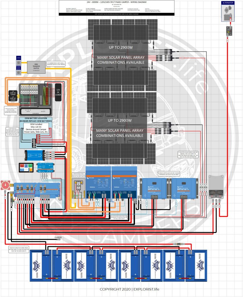
This DIY camper solar wiring diagram and parts list is a high powered system capable of delivering up to 6000w of power through 120V or 240V split phase (3000w through each L1 & L2. This diagram is also capable of charging via solar at a rate of up to 2900w per charge controller added.
This diagram features:
- Dual 3000W Inverter Charger
- 800+ Amp Hours (@12V) of Battery Storage Capacity in a 24V Battery Bank
- Virtually unlimited Solar Array Capacity
- Alternator Charging (100A)
- Shore Power Charging/Passthrough
**Disclaimer & Managing expectations** Setting up dual inverters is NOT a ‘beginner friendly’ task. It DOES require some programming via computer to sync the dual inverters so they will deliver 240V split phase properly (2x 120V legs, 180 degrees out of phase). If you don’t understand the concept of the phrase you just read (and are unwilling to learn this concept)… this setup may be a bit too advanced. That said… here are some good resources that talk about some of the nuances of dual inverter setups:
- https://www.victronenergy.com/live/ve.bus:manual_parallel_and_three_phase_systems
- https://player.vimeo.com/video/372986305
- https://shop.pkys.com/Setting-up-parallel-and-split-phase-systems-using-the-Victron-MultiPlus-and-Quattro-inverter-chargers_b_161.html
**PLEASE READ ALL USER MANUALS BEFORE ATTEMPTING THIS INSTALL**
Not quite what you are looking for? Check out other system setups here: https://www.explorist.life/solarwiringdiagrams
History of Changes to this Page (Click to Expand)
Post Published December 10, 2020
TABLE OF CONTENTS
HOW TO USE THIS PAGE – VIDEO
This orientation video will show you how to best use this page to build your DIY Camper Solar Setup. It’s a quick watch but I think it’s pretty important.
DIY Camper Van Wiring Diagram
DIY Camper Solar Parts – Shopping List
The list below is a consolidated parts list for this entire system (Minus the solar charging leg, as that varies greatly from system to system. If you need help designing an appropriate solar array for this system, consider joining the EXPLORIST.life private group: https://www.community.explorist.life ).
For the ‘Quantities’ in the below shopping list, each singular component is listed a quanty per each, wire is listed a quantity of feet, and heat shrink is listed as qty 1 = 2.25″.
For Example:
Qty 1 – Inverter Charger means you need to purchase 1 Inverter Charger
Qty 3 – 4/0 Wire means you need 3 feet of 4/0 wire. This may mean you need to buy 5ft from the product page
Qty 5 heat shrink means you need 5 pieces of 2.25″ heat shrink. This means you’ll need 5 x 2.25″ pieces of heat shrink for a total of 11.25″ of heat shrink.
Camper Solar Parts Detail
The section below will tell you where each of the parts from above fits into the wiring diagram. This is quite lengthy, but if you are having trouble seeing the diagram or just want more clarification that the diagram above doesn’t deliver, hopefully this will help:

18 Responses
I am upgrading my camper to dual 12/3000 Multiplus inverter/chargers. Each inverter will be powering it’s own set of circuits. We are off grid so the only power to the inverters will come from the batteries or Onan 5500 watt generator. We have 4,100 Watts of solar on three victron smart MPPT chargers. The generator does single phase 120volt output. I think given won’t have this ever plugged into shore power I don’t need to run split phase on the inverter/chargers and can just run them parallel. The only downside I think I have is that if we get into a situation where the generator needs to run, one multiplus will take AC input from the generator and charge while the other will simply continue to power from the batteries. Can you give me a gut check to my thinking?
The single phase 120V generator would indeed feed into Multiplus on L1 and pass that power through to the L1 loads AND recharge the battery bank. The loads on L2 would indeed just come through the L2 Multiplus Inverter being pulled from battery power.
If at all possible…I’d strongly recommend consider a 24V system like shown in this post you commented on. Attempting to pull 6000kVa from dual multiplus 12/3000’s could result in pulling nearly 500 amps from the battery bank which is more than I am comfortable with recommending. Switching to a 24V batttery bank would half that amp draw.
Also, could you have used 1/0 to connect the batteries together? Everything I’ve studied says you can use smaller wire as voltage increases.
Many thanks!
Yes, that is suitable given the 24V battery bank here.
Hi Nate! Did you use 4/0 wire for other technical reasons? Page 10 of the 24|3000 Multiplus manual shows that 1/0 wire is sufficient.
I used 4/0 because I found people using this diagram… except using a 12V battery bank and then burning up the 1/0 wires. No, that’s not a good ‘technical’ reason, but was the best stop-gap I could come up with to keep people a bit safer. You can indeed us 1/0 for the 24v 3k multiplus.
Nate, I am building 12volt dual 3k Multis system (I know 24V would have been much better) and have a question on connecting my 6-100AH Battleborn bank to a Lynx Distributor. What size wire does this need to be and if dual 4/0 is needed how would 2 of those connect to the Positive lynx bus bar and 2 grounds on to the smart shunt?
It would indeed be dual 4/0. You’ll have to figure out the connection on your own since I don’t really recommend doing what you’re doing. 👍
A few questions arise from this:
#1: Why go with the Dual 3K invert over the 5K Quattro(which has 120V 240V Split Phase) – other than the obvious -1K output difference
#2: Speaking with Battleborn – they have an aversion to 24V systems, due to “balancing issues”. Thoughts?
Hey Eric!
1: The Quattro does not have 120V 240V split phase. If 120V/240V split phase input/output is desired, 2x Quattro’s would need to be used similar to the diagram on this page. There ‘was’ a 120V/240V split phase Quattro about 10 years ago; but it was discontinued at some point and is no longer available.
2: My ‘thoughts’ are that as long as they say that “Battle Born Batteries are capable of being connected in series up to 48V” in their user manuals, it is fine. If they are TRULY averse to wiring their 12v batteries in series or series parallel to make a 24V battery bank; they would put that in their documentation.
Hello, for power distribution center you suggest PD55K000 in this page. Is that the correct one because PD55K000 is 10 Dual (50Amp 240VAC)? If all it gives is 240VAC, how am I going to use the 120VAC loads? Would I just use one half of the double pole breaker?
You’d just use a single breaker as opposed to a dual breaker for 120V loads. 240V split phase circuit is made up of 2x 120V circuits and you can use just one of them for 120V loads; just like in your house.
Thanks for this! It helps a lot.
In the “Battery Bank to Busbars” there is a 400a fuse, but the disconnect is only rated to 300a. Is that a concern?
Nope. The actual anticipated amperage flow of this system is about 250A. The switch is sized for that.
I’m looking for help with my build that may be similar to this. Where can I contact you for specifics to my build? Thank you for your time.
I have a private group set up for answering questions that may be more in-depth or personalized than I can provide here in the blog comment section. More info on that here: https://community.explorist.life
I am not able to print the drawing using Adobe. The drawing would be better if you didn’t have the grid. I feel that I have wasted $9.99!
Sorry you are having issues. I print each of my diagrams before they get pushed live including this one. I actually have this one printed out at 24″ x 32″ on my wall. For this reason, I have significant reason to believe that this is an issue with your computer/printer and not my diagram but I am not sure how to help you troubleshoot computer/printer problems. If you tell me more specifically what is going wrong, perhaps I can give a suggestion.