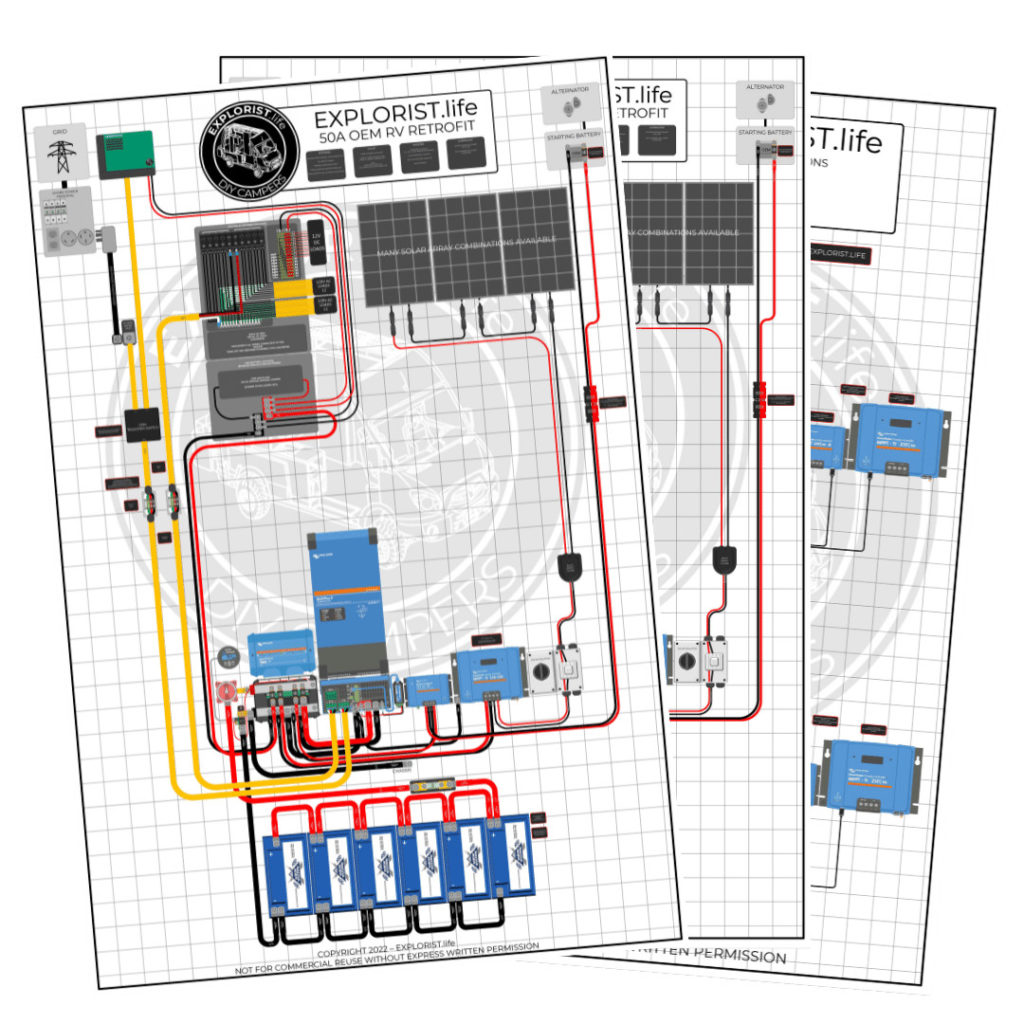
This blog post is going to teach you how to add an Inverter, Alternator charging via DC-DC Charger, and Solar charging to your OEM camper or RV that came factory installed with 50 amp shore power hookups.
This setup will allow for 120V appliances/devices to run on shore, generator, OR battery power. 240V appliances will run on Shore/Generator only (and will need a 120V/240V compatible breaker box (Not shown below).
This diagram features:
- 3000W Inverter Charger
- 400+ Amp Hours of Battery Storage Capacity
- 400W-1200W Solar Array Capacity
- Alternator Charging
- Shore Power Charging/Passthrough
50 Amp OEM Camper Electrical Upgrade Wiring Diagram
CLICK HERE TO PURCHASE THE HI-RES PRINTABLE PDF OF THIS DIAGRAM
50A Camper – Inverter w/ Solar & Alternator Charging Upgrade Shopping List
The following list will show you 98% of the items you need to install this system on your camper. If you need clarification on where something goes, please refer to the ‘Detailed Parts List’ below this consolidated shopping list. Also, you will need to refer to the solar array wiring diagrams at the bottom to add the appropriate solar array parts to your system below.
A NOTE ABOUT QUANTITIES
For the ‘Quantities’ in the below shopping list, each singular component is listed a quanty per each, wire is listed a quantity of feet, and heat shrink is listed as qty 1 = 2.25″.
For Example:
Qty 1 – Inverter Charger means you need to purchase 1 Inverter Charger
Qty 3 – 4/0 Wire means you need 3 feet of 4/0 wire. This may mean you need to buy 5ft from the product page
Qty 5 heat shrink means you need 5 pieces of 2.25″ heat shrink. This means you’ll need 5 x 2.25″ pieces of heat shrink for a total of 11.25″ of heat shrink.
Qty 8 – 2/0 x 5/16″ Wire lugs means you need 8 wire lugs… not 8 packs of wire lugs.
50A Camper – Inverter w/ Solar & Alternator Charging Upgrade Parts Detail
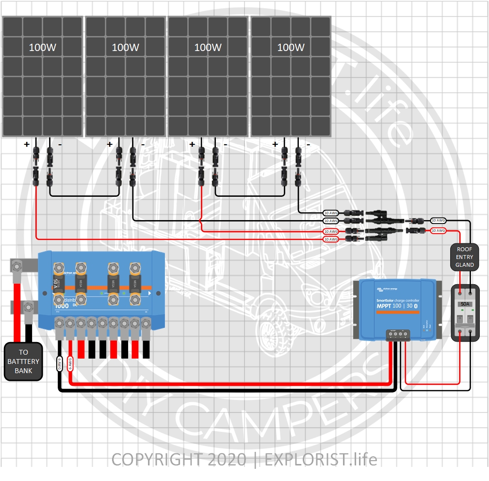
Choosing your Solar Panels & Charge Controller
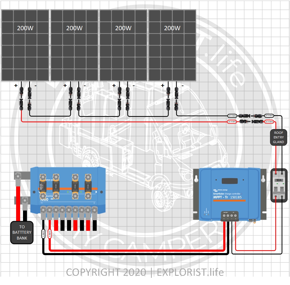
The following section provides you with several different options for solar charging. The above parts list can remain completely unchanged and the diagram above can remain mostly unchanged except for the alterations noted by the diagrams below, but whatever solar array setup you choose below for your needs, these parts will need to be added to your shopping list. These are broken up by total solar wattage. As a general rule, you want to have twice as many watts of solar as you do amp hours of batteries. So, 300Ah Batteries = 600W solar. 400Ah Batteries = 800W solar. 600Ah Batteries = 1200W of solar. This is just a rule of thumb. Not a law.
400 Watts – 4x100W Solar Panels – 12V Battery Bank (Click to Expand)
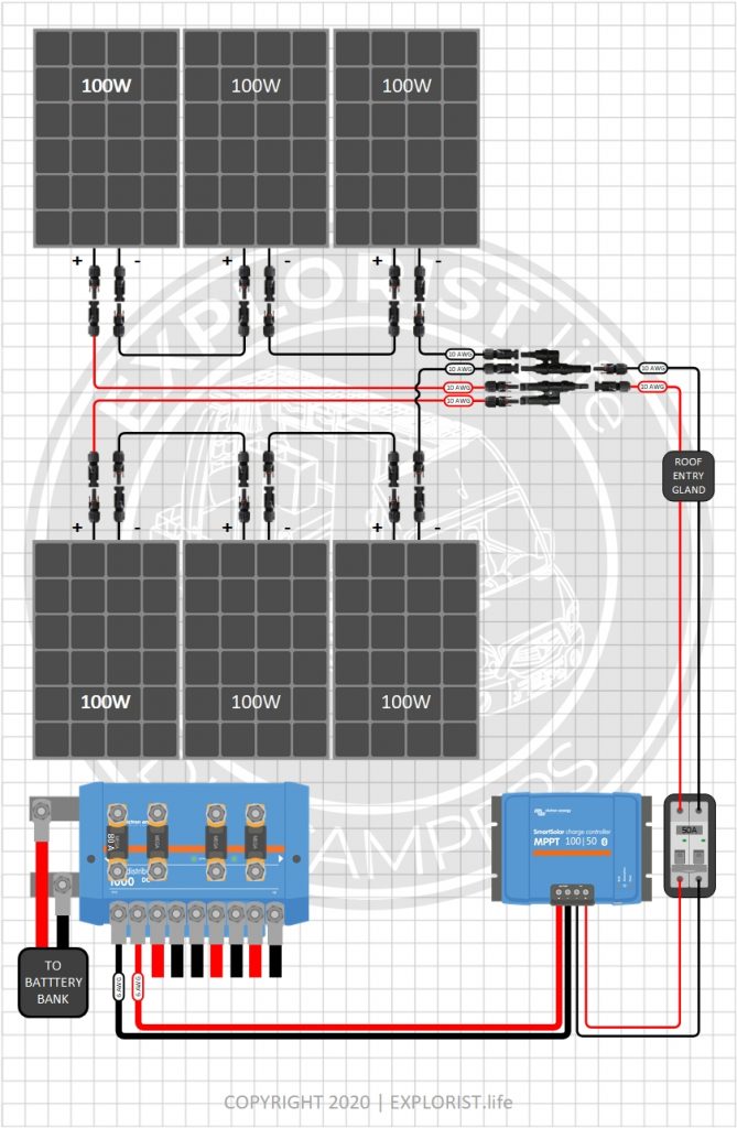
600 Watts – 6x100W Solar Panels – 12V Battery Bank (Click to Expand)
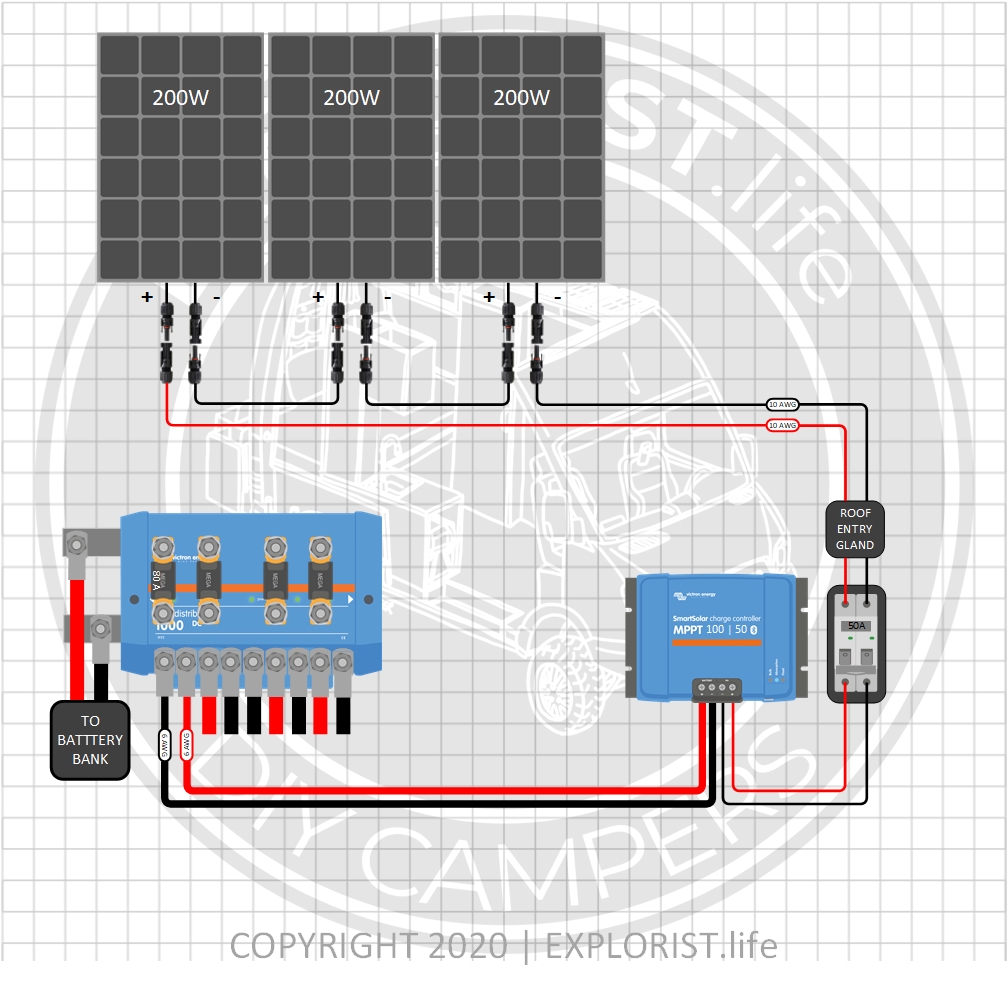
600 Watts – 3x200W Solar Panels- 12V Battery Bank (Click to Expand)
800 Watts – 4x200W Solar Panels- 12V Battery Bank (Click to Expand)
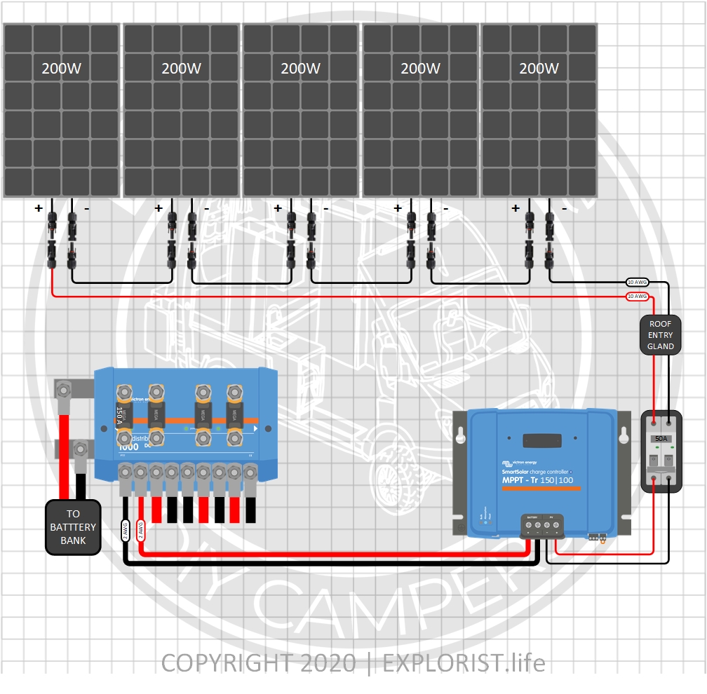
1000 Watts – 5x200W Solar Panels- 12V Battery Bank (Click to Expand)
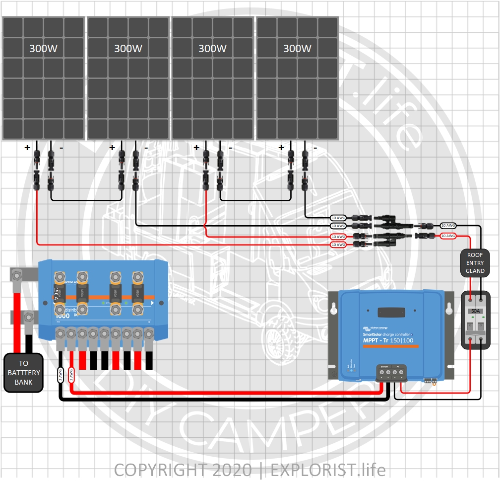
1200 Watts – 4x300W Solar Panels- 12V Battery Bank (Click to Expand)
How to Integrate a DIY Camper Electrical Upgrade with the OEM Wiring
The following section of this blog post will teach you how to integrate the wiring diagram and parts list above with your RV’s OEM electrical system.
Here is how the typical camper with 50A shore power hookups is wired:
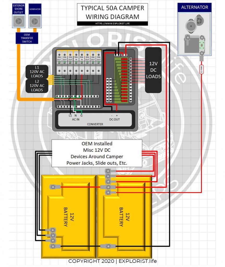
- The diagram above shows the typical bare-bones OEM RV/Camper with 50A shore power service.
- Shore power flows into the breaker box, powering the breaker box protected by a 50A breaker where 240v power is divided up into 2 legs of 120V power to power both sides of a breaker box
- One circuit is generally the Converter. The converter is usually built into the same enclosure that houses the breaker box (as shown) but is sometimes external. Either way, it’s wired in the same method.
- The converter converts the 120V AC power to 12V DC power which feeds the DC Fuse Block which powers the various DC devices around the camper (Lights, Fans, Etc..).
- From there, a positive and negative wire continues on to the house battery bank; usually two 12v batteries wired in parallel. These wires charge the batteries from shore power, and allow 12v devices to run when not connected to shore power.
- At the batteries, there are usually 2+ additional positive and negative wires heading off under the RV somewhere that are going to power additional DC circuits around the camper. These may be slide-outs, powered leveling jacks, and other ‘chassis’ items like that. These wires will likely have fuses in line to protect these wires coming from the battery.
- One of these wires is also likely the wire coming from the alternator to charge the house battery bank.
When the camper is NOT plugged in to shore power, all of the 12V DC appliances will run due to them still being connected to the batteries, but the 120V AC appliances will NOT operate because the converter is a one-way-street and will not convert 12V DC back to 120V AC. The charging from alternator is typically very slow (less than 10 amps) and should, generally, not be relied on to provide adequate power for recharging deeply depleted house battery banks.
In addition to wiring the components together, here is a breakdown of how the flow of power to the above diagram works.
WIRING THE INVERTER/CHARGER To Shore Power.
When connected to shore power or generator, power flows from shore power (or generator) to the inverter charger. This charges the batteries which feeds the DC fuse block and allows 50A shore power passthrough to power the 120v appliances. You will take the 6/4 wire that goes from the shore power inlet to the back of the AC distribution panel and instead, run that wire from the shore power inlet to the input of the Victron Multiplus.
Wiring the Inverter/Charger AC Distribution Panel
The 6/4 Wire from the AC Out of the Inverter/Charger will go to the same place that was just mentioned in the above step.
Wiring the Solar Panel Array to your Camper Electrical System
When charging from solar, the solar panels & charge controller charge the batteries. The batteries are connected to the DC fuse block allowing use of the 12v devices around the camper. The Inverter takes the 12V DC power stored in the batteries and converts it to 120V AC power to power the 120V AC items around the camper.
Replacing Stock Camper Batteries with Busbars
A positive and negative busbar take the place of the stock batteries in the stock battery location (assuming that upgrading batteries means you will not be able to store your new battery bank in the stock location). From the Lynx Distributor, power flows to these two busbars where power is then sent to all of the OEM installed components like the DC distribution block, power jacks, slides, etc.
50A Camper Converter
The OEM installed converter must be completely disconnected. It can remain installed, but the wires must be disconnected from both the AC and DC side of the power distribution center. These wires can usually be bundled up and stuffed next to the converter.
50A Camper Alternator Charging
You will likely have a wire charging your OEM batteries from the alternator. This wire will likely be somewhere in the 12 AWG range. This will either run directly from your starting battery isolator if this is a motorhome or from your 7-pin connector if this is a trailer. This needs to be disconnected completely. This diagram uses a 30A DC-DC Charger and the OEM installed wire will be too small. The 6 AWG wire in the diagram will take the place of the OEM wire you are to remove. In the case of a trailer, 6 AWG wire will need to be run all the way to the truck starting battery if alternator charging via DC-DC Charger is desired and disconnected by the hitch by means of an Anderson connector. If you do not wish to charge via the Alternator… this entire leg of charging can be omitted without ill effects.

131 Responses
Thanks for all you do, Nate. I’ve practically lived on your site and your 50amp electrical upgrade diagram as I do this install. A quick question… from all that I have read and seen in your solar builds, you wire a breaker between the solar panels and the charge controller but this diagram shows an isolator, no breaker. Can you help me understand why no breaker is needed and what would constitute the isolator being swapped for a breaker. Thanks again!
https://youtu.be/FbwxUedCe-c
Nate,
Love the site and all the education we have received. We are using your 50A retro diagram. We are installing a multiplus-II 2x 120v. I will connect the Ac out-1 to the 50A breaker in the OEM slot on the panel. Where would I AC Out-2? Would this only go to a separate sub panel? Would you generally use it in this application?
AC out 2 is for a breaker box powered only when shore power is connected. I don’t really ever use that.
Do you have a Victron 24/3000 wiring diagram for a 50A 120V L1/L2 factory panel? This is closest to my setup. The 24/3000 x 2 for 6000W is overkill for my needs.
As of writing this reply, the Multiplus 2x120V for 50A L1/L2 Factory panels does not exist in a 24V version. The 12V version does as shown in the diagram on this page, so just use that without changes.
Is it acceptable (from a code and safety perspective), to connect the ANL Fuse holder (with 400A fuse) directly to the battery disconnect (using one of the copper bar adapters)? This would then only mean 1 length of 4/0 positive wire instead of two separate lengths.
I understand that it is important to keep both the positive and negative total lengths the same for balance.
It’s best for the fuse to be as close to the batteries as possible. Here’s what ABYC has to say about that:
11.10.1.1.1 Overcurrent Protection Device Location – Ungrounded conductors shall be provided with overcurrent protection device(s) within a distance of seven inches (178 mm) of the point at which the conductor is connected to the source of power measured along the conductor (see FIGURE 8).
EXCEPTION: If the conductor is connected directly to the battery terminal and is contained throughout its entire distance in a sheath or enclosure such as a conduit, junction box, control box, or enclosed panel, the overcurrent protection shall be placed as close as practicable to the battery, but not to exceed 72 in (183 cm).
Great plans! These really helped me, thanks for you work!
I do have a few questions:
1. Can I remove the components for the alternator charging including the Orion-Tr DC-DC charger? I feel the solar will outperform the alternator charging most days.
2. Would I need a soft-start device for running an A/C?
3. How expandable is this system? I’m planning on starting with the 1200W panel array and 6 Battle Born 100a batteries.
1: Yes
2: Maybe. You could always try without and then add it if you are tripping breakers.
3: Very. You can add as many charge controllers through additional lynx Distributors as you need and you can easily go from 600Ah to 1620Ah of batteries just by going from 100Ah batteries to the 270Ah Battle Born GC3’s.
Hi Nate, I am in the middle of installing this 50 Amp system with all Victron components, including the Multiplus 2. I picked up an ANL fuse holder from your site. Thanks I couldn’t find what I needed anywhere. My question has to do with my Grand Design Momentum. The 12v 6 Ga. positive wire for the DC distribution panel was ran from it’s location inside the pantry to the front bay of my RV and landed on a bus bar that tied to the batteries. However the 12v negative line that would accompany the positive line is nowhere to be found. Any idea how Grand Design may be wiring this RV? I can run a new 6 ga. wire to the DC panel (not fun) but am curious why Grand Design didn’t? The factory setup had the batteries connecting to a bus bar and that bus bar had a 6ga wire going to a chassis ground location. Is it possible they just tie the DC distribution panel to the chassis and utilize the chassis as the “wire”? Thanks in advance!
I don’t know where it goes, but it shouldn’t matter. In this diagram, you’re simply running power from the Lynx Distributor to the OEM battery location to supply power to all of the OEM equipment so we don’t have to worry about ‘how’ Grand Design wired anything.
Hi Nate. This a great fit with my situation. My OEM (travel trailer) uses a positive bus bar and a chassis bus bar. Everything old and new within 3 feet of each other. Is there an advantage in using the OEM chassis bus bar for grounding from the Lynx 1000 over establishing a new chassis ground?
That should be fine providing adequate wire size as shown in the diagram.
Hi Nate,
I currently have a 30A TT, but might be interested in upgrading to a larger 50A someday (5th wheel). After looking at your two diagrams, I noticed a lot of similarities, and you switch the 30A breaker to a 50A in the 30A diagram. Is it possible to set my 30A trailer up with the 50A system (not using it’s full capability) so that someday I would not have to replace components other than to increase the PV array and battery bank to accommodate the larger trailer requirements?
Also, thanks for all the educational info!
I would personally just build the proper system for 30A and then sell that system with the RV and then build the correct system with 50A when you get it.
Hey Nate – planning ahead for end of 2022 summer upgrade of trailer. Wondering when you may have diagram ready for 50AMP replaced with the new Multiplus?
It’s ready! Check the update.
Hi Nate, on your 1000W panel kit shown above – could an additional 200W panel be added to get to 1200W rather than use the larger size 300w panel used in your 1200W layout? Would the other components still support? was thinking keeping it all parallel or 3S2P.
Here is how 6x 200W panels would look: https://shop.explorist.life/shop/all-products/camper-wiring-kits/solar-charging-wiring-kits/1200w-solar-charging-wiring-kit-6x-200w-12v-battery-bank/
Nate, looking at the 50-amp OEM Solar retrofit wiring diagram, it shows two charge controllers. One from the array and one from the alternator. If I have a 200-watt briefcase in addition to the roof array, I would have to add another charge controller for the briefcase, correct?
Because of space constraints, I am looking two arrays, an 800-watt array made of four-200 watt panels wired in series/parallel, with the second array at 400 watts consisting of 4-100 watt panels also wired in series/parallel. I assume this configuration would require two charge controllers rated for the voltage and amperage or each array? Is there an easier way, as I am looking at four charge controllers or is that normal?
That’s correct. 1 charge controller per solar array.
The Master Disconnect is a 300 amp switch. Is it big enough for this application? Do I need to up grade to the 600 amp switch?
300A is plenty sufficient. I explain why at about the 14:30 mark of this video: https://youtu.be/01F4QDVJUq0?t=869
Thanks for the excellent diagram. One question though, why the 6/3 wire on the AC1 output?
With only a 30 amp input, using 10/3 wire, and a 30 amp main shown in the diagram on the RV panel, would you ever pull 50 amps?
I know the maximum passthrough is 50 amps, but how could that ever happen?
I know a fault in the 6/3 wire could potentially pull more current but I’m unclear on the need for 6/3 vs 10/3.
Thanks for clarifying for me if you have the time 🙂
This diagram is for systems with 50A shore power; which would be 50A on both L1 and L2 incoming using 6/4 wire.
Love your site
I am very interested in upgrading my vintage 30 amp system to the 50 amp system with a future expansion to solar power. I currently have a 30 amp shore and generator setup with a converter. Can I purchase a printable plan from you?
Sure! You can purchase whatever you like from me. 🙂 shop.explorist.life
Is it recommended to upgrade the firmware when installed the new Victron Multiplus II?
The firmware should indeed be updated on initial installation.
If I wanted to have a larger panel array, say, 1800-1900W, would I need to do anything other than stick a larger charge controller in here?
For more than 1450W of solar, you’d need multiple charge controllers: https://www.youtube.com/watch?v=N0UB7LZVduk
Hey Nate! Thanks for your help with all your info! Any reason I can’t bolt the ANL fuse to the battery switch using a set of your copper adapters?
You could likely do some arts and crafts to make it work. The main issue is that the connections aren’t really on the same ‘plane’ and wont sit flat without a fair amount of shimming the components up to flush.
Hey Nate,
Thanks for the 50 amp wiring diagram. I purchased the printable version and it has been a life saver for me. One question, the diagram shows 6/4 wire going from the Magnum inverter to the A/C distribution panel, but the diagram shows 6/3 wire, or am I missing something. What 6/4 wire would you recommend for the connection from shore to inverter and then from inverter to distributional panel/
Sometimes you can re-use the OEM wiring, and just go from the transfer switch to the Inverter/Charger instead of going directly to the Breaker box. If not… Here is some 6/4 wire: https://amzn.to/3vkD4y9
Hi Nate, You don’t realize how much you have help me with up grading my motorhomes electrical system so thanks. I am not a electrical engineer/person but with advice from smart people like yourself I enjoy being a DIY person working on and learning about my 50 amp motorhome. Over the past couple years I’ve been up grading my electric system with solar and other Victron pieces and now I’m ready to finalize my project with lithium battery bank. I am following your 50 Amp OEM Camper Electrical Upgrade Wiring Diagram for my MH. One of my questions is this; I am going to end up with 1200 amp lithium battery bank so am I ok with using the same size fuses in your diagram or do I need to increase my fuse sizes? Thanks for the help. Rick
Battery bank capacity doesn’t affect fuse size.
Nate, I came across 8 3.2v 280ah batteries. I would like to make 2 12v 280 Ah batteries then parallel the 2. My question is the BMS set up do I need 1 for each battery? Any suggestions on the rest of the equipment need would be appreciated also. I.E. MPPT charge controller, shunt or shunts, an active cell balancer or 2.
My plan includes 4 200 watt mono panels. Any and all ideas will be awesome. I do like the Victron equipment but not sure how deep I want to go.
You would want to reach out to the battery manufacturer for proper BMS configuration. Once you get the battery bank sorted out, this diagram would get everything sorted out for the rest of the components downstream of the battery bank.
Love to see the new Victron MultiPlus-II 2x 120V swapped in here
As soon as it is readily available for purchase, I will swap it in.
@Nate Yarbrough, it looks like it is now available on Amazon. I’m also interested in the Multiplus II as it is great upgrade for 50A Rvs IMO.
Diagram and parts list updated. 🙂 Check it out!
@Nate Yarbrough, Any update on this. I am about to embark on a 1.68KW solar install with the new multiplus-II 2x 120v. Purchased this diagram which is great but it would be awesome to see it updated with the new unit that many RV’ers with 50amp service will likely use.
Also your YouTube videos are AMAZING!
Thank You@
It’s been updated! Check it out. 🙂
Nate, I have a Victron Multiplus ll 120/240 on order with the Smart shunt, Cerbo GX and color monitor. In a comment below you mentioned that you will be updating this system to include the new Victron. When do you think that update might be out?
It will be out once the unit is readily available for purchase. Basically, as soon as Battle Born adds it to their store and is ready to ship, I’ll update the diagram. (I don’t like making diagrams that include parts that people cant get.)
@Nate Yarbrough,
Can you update this diagram with the Multiplus II? Can you also tweak it a little for my setup? I am using 2 Victon 100/50 controllers and the Cerbo GX with Touchpad.
Diagram has been updated with the Multiplus II.
Cheers!
Hey Nate! Thanks for your info! Curious why the DC to DC diagram shows the negative connected to the battery, could you connect the negative to the chassis ground closer to the DC to DC itself?
If you are talking about the starter battery, it’s because that’s what Victron recommends on pg 5 of the user manual.
My factory positive battery wire goes to a mini breaker buss bar before it powers the slides and jacks. Do I leave this in the system or replace it with a buss bar?
You should just be able to leave that as-is and power the mini breaker bus bar from the Lynx Distributor.
You have 6 awg coming off of the lynx distributor at 2 points but one has a 50 amp fuse and the other has a 100. Is this correct or a typo? Shouldn’t they both be 50?
It’s correct.
This fits perfectly with my planned install. My question involves the remotes devices. The BMV712 I get as any system should have such a device. But the diagram does not indicate the remote for the Magnum MSH3012RV or the MPPT controller. For the Victron components is a GX device needed, desireable or just a waste of money? Can I get all I need from the Victron App? If desired or needed which would you recommend? I see that you recently changed the inverter/charger to the Magnum RV model… why it over the other hybrids out there, Victron GO POWER, Xantrex? I’m weighing the GP and Magnum units. I’m sensing the new Multiplus II will be underpowered for my application and I don’t want to have two inverters.
The Smartsolar MPPT and the BMV-712 will communicate via bluetooth and can be monitored via the VictronConnect app. The Magnum does not natively communicate with these devices. The 120V/240V Multiplus coming out at the end of this month (March 2021) will be able to communicate. The GX devices are FANTASTIC but are more of an ‘optional’ add on. I try not to add stuff to these diagrams unless I feel they are absolutely necessary.
I chose the Magnum for this diagram over the Victron as Victron does not have a 50A 120V/240V Inverter/Charger on the market (There is one coming out at the end of this month, March 2021 and the diagram will be updated to reflect that.
Hello Nate, I’m following this 50A OEM retrofit, my question will be on the solar charger side. Are there any advantages or disadvantages to running 2 100/50 MPPT charge controllers vs. 1 150/100 charge controller? 6 210W panels, 3 panels in series produce (from your calculator) 70.09 max array voltage, and 43.75A max charger output. All 6 in series 140.2V @ 87.5A. Series parallel will be 70V and 87.5A. Two 100/50 MPPT chargers are less cost then the 150/100 charger.
That is fine and is compatible with this diagram, you would just need to make sure you have enough spaces inside of the Lynx Distributor to house both charge controller circuits and if you don’t… you can buy an additional Lynx Distributor as they simply bolt together for an additional 4x spaces.
Glad I found you! Great resource.
Hey Nate,
Why did you go with the Magnum inverter/charger vs the victron on this diagram?
I chose the Magnum because, currently, Victron does not have a 50A 120V/240V Inverter/Charger on the market. There is one, though, coming to the market at the end of this month (March 20210) and I will be changing the diagram to include that unit once it is available to purchase.
Hi Nate,
First of all I would like to thank you for all the great content you have put on the web! It has helped me tremendously to understand the various electrical components and how they interact, and am about to get started on a batteries and inverter install on my RV largely thanks to you.
I have purchased the 50A OEM RV RETROFIT SOLAR UPGRADE – WIRING DIAGRAM and have noticed that the ground cable between the solar charge controller (to which the inverter ground is also connected) and the Lynx distributor is 2 AWG; however in your recent video “How to Install Solar & Electrical in a DIY Camper (A Complete Walkthrough)” you explain that the ground cable shouldn’t be smaller than one size smaller of the wire used, and recommend using 4/0 to connect the inverter to the ground.
So I was wondering if the 2 AWG cable in the diagram between the solar charge controller and the lynx distributor ground shouldn’t also be 4/0 ?
Best,
Sinan
That’s a great catch. The Magnum inverter/charger shown has a screw terminal equipment ground that can accept a max wire size of 2AWG so it’s not possible to wire the equipment ground of this piece of equipment as described in that video that you are referencing, but since it’s still within manufacturers recommendations, it’s fine although not necessarily compliant with ABYC standards.
Can the disconnect and shunt be directly bolted to the Lynx distributor? Look like the hole in the Lynx would need to be drilled out slightly.
Although I’m not comfortable recommending modifying a piece of equipment (for the sake of my own liability), if you were to drill those holes out to 3/8″, the switch and shunt would indeed fit.
Hey Nate,
I just came across your YouTube channel last week while watching Andy Rawls Airstream remodel. I really appreciate your videos and all of the information you posted on here! I’m currently remodeling a old Argosy Airstream and I’m planning on putting a 50A service in it with 5 Go Power Overlander-E 190W Solar panels ((Vmp)19.11V,(Imp)9.3A,(Voc)22.78A) on top running the Victron 3000 and 500ah Battle Born lithium.
Do you think that I could get by with the Victron SmartSolar Charge Controller 150V 70A Tr? Not sure if I calculated everything right but this model is on sale right now for $470 so I was hoping it would work.
Just started the planning phase for the electrical system and are working on my diagrams. After I get those together would I be able to hire you to look over everything and to make any needed corrections?
Thanks
Jude
Hey Jude! Here is how to size a charge controller. This should get you on the right path: https://www.youtube.com/watch?v=MxziHKvTRh8
If your diagrams are based around my designs, I can indeed check over them in my private group. More info here: https://community.explorist.life
Hi Nate,
Why are you using a 50 amp DC breaker from the panels to the charge controller on 10 AWG wire? If I understand correctly, 10 AWG is rated at 35A, 75 degrees?
Thanks
Erik
That is used only as a disconnect and is offering no overcurrent protection in that position. It is sized so large so it will never automatically trip.
Hey Nate,
I am looking at the Magnum Hybrid inverter chargers due to their ability to take power from shore and battery simultaneously. This is nice where only 30A or 15A options are available. Does Victron have this capability? Overall, I like Victron better, but like the idea of hybrid functionality.
If I go with the Magnum setup, would it support expanding to a second inverter in the future? I’m trying to decide between this diagram and your dual Victron split phase diagram.
The Victron Multiplus does indeed have that function through it’s PowerAssist function.
I ***believe*** the Magnum inverters can be run in parallel, but you should do your due dilligence on that. Victron Multiplus inverters can for sure be run in parallel (as you found in my other diagram).
I would NOT recommend ‘adding’ an inverter to this setup as that would bring you to a potential of 6000w of inverting capacity which is 500A which exceeds the limits of this diagram. If that much inverting capacity is desired, I recommend this 24V setup: https://www.explorist.life/24v-6000w-120v-240v-split-phase-camper-solar-wiring-diagram/
Hey Nate,
When I replace the OEM batteries with the bus bars do I leave my existing 1000 watt inverter that was powered off of them in place?
Thanks, Terry
I would recommend uninstalling the 1000w inverter altogether.
For the solar set up what is the maximum wattage of solar panels that you recommend for the 50amp one retrofit with 6 battle born batteries. And would the 50 amp fuse and mppt charge controller need to be changed? Thanks so much
For 600Ah of batteries… I would recommend 1200W of solar panels. There is a 1200W solar array example near the very bottom of this blog post that would work with this 50A retrofit diagram: https://www.explorist.life/3000w-inverter-400-600ah-400-to-1200w-solar-camper-solar-kit
What’s your opinion of the Renogy 60A MPPT vs Victron/Magnum?
The VictronConnect app data reporting for the Victron Smartsolar Controllers is why I recommend the Victron SmartSolar line of charge controllers over all others.
What software do you use to draw your diagrams?
I use Microsoft Visio to make my diagrams.
Hi Nate. In the 800 watts solar panel section, you show 4 panels wired in series. Is there any reason you did not show them wired in series / parallel so a smaller charge controller could be used?
I own a 5th wheel. Is there any issue driving down the road and charging the batteries off the alternator at the same time the solar panels are charging the batteries?
Does Victron plan on releasing a 120v/240v Multiplus? If so, do you have a timeframe?
Thanks
Dave
A smaller charge controller could not be used even if the array had a lower operating voltage as it would exceed the maximum allowable output amperage of any of the 100V charge controllers.
Hey Nate! I just purchased the 50A Solar Rv and Im wondering about one thing. Ill be doing a bus conversion so I’ll be doing the power bank from scratch. Im building a 24v 800ah bank(bottom balancing the LiFeO4 batteries first and building them in 8 packs X 4. In a different video I watched where the gentleman did a full vistron setupv with a 400ah bank, he fused the individual battery packs and then ran those to Victron 100A battery protects, then from there to + and – busbars, then the + to the to the multiplus, the – to a shunt then to the multiplus. He didnt run them to a distributor first. Then he followed the rest of the same diagram. Do you see a problem with doing it that way?
I recommend following the diagram as I’ve designed it on this diagram. If you feel the need to change it, that’s fine; but that’s up to you and the level at which you grasp system design.
Hey Nate, love your wiring diagrams. I noticed the parts list includes 6/3 wire but the wiring diagram shows 6/4. With 120v/240v split phase inverter and 50A service shouldn’t it be 6/4 wire?
From the shore power inlet to the inverters (well… the breaker…) it is 6/4. From the inverters back to the AC Distribution panel, it is 2x 6/3.
@Nate Yarbrough, thanks for the quick reply. Would a single 6/4 wire from the Magnum inverter back to AC dist panel work just as well as the wiring diagram shows or is it recommended (for some technical reason) to run 2 separate 6/3 wires?
Oops. Sorry. I thought we were commenting back and forth on my dual multiplus setup. For this diagram we are looking at on this page, it would indeed be 6/4 both to and from the inverter charger.
Hey Nate,
I am following your “How to Install Solar & Electrical in a DIY Camper”. This will be an upgrade to a new Jayco Travel Trailer. I have purchased the following. Victron MultiPlus 3000, Lynx Distributor, SmartSolar MPPT 150/45, BMV 712, Color Control GX, & Digital Multi Control, Battle Born Batteries, 4 100W Renology Solar Panels. I decided to setup a test bench to test everything prior to installing in trailer. Your wiring diagrams are Great. Thank You. I have 1 issue maybe you can help with. Everything works great charger, inverter, (tested with 1785 watt Coffee maker) solar charging & all monitoring devices. Here is the issue. I have to switch the Blue Sea Switch on & off twice in quick succession for battery power to stay on. Using both a Multimeter & 12v test light, the first time I turn on the switch, voltage passes thru & immediately drops to nothing. Almost like a short. This occurs all the way to the batteries. Not even any voltage across the Battle Born terminals. But If I turn the Blue Sea switch on & off twice rapidly the voltage stays normal & everything operates just fine. I have quadrupled checked all connections, wiring, etc. All correct. Never any blown fuse or anything. I have tested the Blue Sea switch with an MultiMeter, Ohms & voltage no issue seen. I’m confused. Maybe a issue with the internal Battery Monitor in the Battle Born batteries? Inverter? Thanks in advance.
Are you, by chance, using 3 or fewer batteries?
I was reviewing your wiring diagram using the Magnum inverter/charger. My 2020 Tiffin Allegro came from factory with the MS2012 12V 2000W inverter/charger. Can this unit be used in place of the 3000W unit you describe?
Thank you
They aren’t the same, no… but it sounds like you’ve already got an inverter, so I don’t think this diagram would help too much?
I have a truck with a 200 amp alternator and pull a 5th wheel. I would like to charge my 5th wheel lithium batteries while I am driving. What are the advantages of using a Victron dc to dc charger over a Renogy 40 amp dc to dc charger?
Victron is working on a firmware update that will allow the DC-DC charger to coordinate charging efforts with the solar array. So… If solar was charging at 50A and the DC DC was charging at 30A, there would be 80A combined. If you mix and matched renogy & victron, it would be one or the other. This functionality is not available RIGHT NOW, but soon…
I own a 2020 Grand Design Momentum 395TH. I have a Magnum Hybrid charger/inverter with 4 Battle Born batteries. I have a couple Victron components (Battery Monitor, Solar Charger.
1: If I purchase your Schematic for the Magnum, Does it come with a parts list with everything I need to install my stuff
2: Does it have wiring for the on board Generator
3: Does it come with some consulting time with you
4: I’ve looked at a lot of sites and can’t find all the information I need. Also, I have a 10 awg wire from the roof to the battery bay. I don’t know how many solar panels I can run on that wire or should I run a bigger one.
I plan on starting the install after around Christmas time.
Thanks
John
Hey John,
1: No, but you already have access to that. It is above under the “50A Camper – Inverter w/ Solar & Alternator Charging Upgrade Shopping List” heading.
2: It should get you 90% of the way there but this diagram is not for your SPECIFIC camper, so there may be some slight differences. But I’m confident that a DIYer with above average mechanical aptitude can figure it out.
3: No. The diagram is just a high resolution diagram of the low resolution diagram found above. Consulting is available here: https://www.community.explorist.life
4: With a properly planned solar array, you can get all 1200W of solar as shown on this diagram with 10 AWG wire from array to charge controller.
@Nate Yarbrough, that link goes to a security warning page and then ends up at an Apache server page??
Hmm… not sure. It’s working on my end. https://www.community.explorist.life
@Nate Yarbrough, You need to remove the “www.” from the url you’ve provided, so: https://community.explorist.life/
Ahh, yep!! That’s it. Thanks!
Where is the ‘Detailed parts list’ mentioned above?????
Under the header: “50A Camper – Inverter w/ Solar & Alternator Charging Upgrade Parts Detail”
Hi
Can I pay with PayPal instead of visa for the diagram
I don’t believe I am set up for Paypal. Sorry about that!
Looking to disconnect (eliminate) the alternator charging of the house batteries. Have a 2020 Jayco 34G Class A. 600w 24 solar charging 2 6v for 224AH Have two Battleborn lithium I want to install without frying the alternator
Great! Just delete the entire alternator charging leg on the diagram ALL the way back to the Lynx Distributor. No other changes necessary.
Hi Nate – I’ve noticed you like to use the Victron Lynx Distributor. It’s truly a great product to simply most installs.
I am curious why you do not use the Lynx Shunt module which would tidy up the shunt setup as well as get you the positive fuse built in?
Thanks for all you do as you are a terrific source of information.
The Lynx Shunt is also a great unit, but it does increase cost & complexity in the system as it forces a user into pairing the Lynx Shunt with a GX device like the Cerbo GX. Bluetooth monitoring directly from the Lynx Shunt is not available like it is with the BMV-712 or SmartShunt.
Hi Nate,
I have been following your youtube channel as I plan my RV battery/solar install. I have purchased a couple of your wiring diagrams, both the 50 amp and 30amp versions. I am planning on deviating from them by going with 2 Victron Multiplus 12/3000 units in split phase. I will be coming off the battery bank positive side with 4/0 cable, to a fuse holder, master disconnect and then into a Victron Linx before distributing to the two multiplus. The Victron Manual states that I need a 400amp fuse, but it does not mention sizing the fuse when you have two units in either split phase or parallel. Do I need to increase the size of the fuse coming off the battery bank to account for two Multiplus possibly drawing 400 amps at the same time? I will have each Multiplus fused at 400amps on the Linx. My concern is blowing the first fuse coming off of the battery.
For dual multiplus setups, I recommend running a 24v battery bank as with dual 3000w inverters… that’s 500A potentially coming from the battery bank (3000w / 12v = 500A). Running a 24v battery bank would cut the amperage demand of the battery bank in half. I will have a diagram showing this made available by the end of the year.
If you are dead set on running a 12v battery bank… you’ll need 2x 4/0 wires and 2x 400A fuses supplying power from battery bank to the Lynx Distributor.
I already have a Victron Multiplus 12/3000/120 that I had installed on a solar setup on my trailer with 30A (with the help of your channel). I have now upgraded to a 5th wheel with 50A service. How can I install this inverter on L1, and basically just not have the bedroom a/c, and then still be able to have full 50A service when plugged in?
L1 from shore would go through the Inverter. L2 would go directly to the L2 side of your breaker box.
@Nate Yarbrough, Why not use OUT-2 for the L2 side of the breaker box?
On the Victron Multiplus… OUT-2 is simply passthrough (with no inverter capability) from AC-IN. There is no way to feed L2 through the Multiplus.
In the victron multiplus 3000 manual it says “The AC input must be protected by a fuse or magnetic circuit breaker rated at 50A or less, and cable cross-section must be sized accordingly. If the input AC supply is rated at a lower value, the fuse or magnetic circuit breaker should be down sized accordingly.” Do I need to wire a breaker in between my shore power inlet and the multiplus? Also what about a surge protector or ems?
The AC Input breaker is housed inside of the campground power pedestal. No additional AC input breaker is required. If you want a shore power surge protector, that’s fine. Here is my recommendation for that: https://amzn.to/2VsKC2o
Thanks for all you do!!
No problem! Happy to help!
Hey Nate,
Thanks for everything you do! I appreciate the wholesome and thoughtful content you provide. I am not sure if this question goes against everything you try to encourage but here goes anyway. I have opted towards going with a solar generator (Goal Zero Yeti 1500x or 3000x) but am struggling to know which one I would really need. After going through your power audit it looks like I’d need about 180 amp hours of battery a day, 400 watts of solar, and a 2000 watt invertor. Both Yeti’s meet those needs except for the amp hours. The 1500x has about 140Ah and the 3000x has about 280Ah which to me seems like I fall between these.
I was wondering if I could get by with the 1500x and up the solar to 600 watts and add an option to charge the battery while the van is running or if it is clear I need to go with the 3000x? I hope this question makes sense and I am sorry if there is any oversight on my part, just trying to make sure I have enough power while being accurate with my estimation.
I’m always going to tell you to go with the unit that actually meets your needs, on paper (3000x). If I recommend the smaller one and you keep running out of power, you’re going to come back and say I made a bad recommendation. If you always have too much power, you’re going to think I make a good suggestion. lol Real world usage can always vary, but it’s near impossible to account for and you’re just going to have to pick one and go with it.
Any changes you recommend from the plans you had with the AM Solar and Victron 12/120/3000 invertor/charger 50A set up?
I am looking at buying those plans in a few weeks to start my build in my TT
The diagram you see above is my best CURRENT recommendation. I opted for this Magnum Inverter/Charger over the Victron paired with the AM Smart Phase Selector because the Smart Phase selector is out of stock for the next few months (as of writing this reply).
Let the Magnum’s start flying off the shelf! This is awesome Nate thank you again for all of this! Those of you that are contemplating joining Nate’s private group? What are you waiting for???!!
Is there any particular reason for the switch from the Victron MultiPlus to the Magnum inverter/charger in your wiring diagram?
Yep! As of today, Victron does not make an Inverter/Charger that is capable of handling 120v/240v split phase. Once Victron releases their 120v/240v Multiplus, I will change out the Magnum on this diagram for it.
@Nate Yarbrough, Is this the one you were referencing in your comment, Victron Multiplus Inverter Charger 3000 W 12 V sku PMP123021102? Wanting to move forward with my 50 amp conversion based on your schematic above and just wanted to confirm as the magnum in your schematic is on back order. Really appreciate everything that you have done with your videos and these diagrams
That inverter is not compatible with 120V/240V 50A shore power.
@Nate Yarbrough, do you know if Victron has a 120v/240v split phase Multiplus in the works? If so, would it do the same thing as adding the AM Solar Smart Phase Selector (SPS) to the current Multiplus model?
BTW, THANK YOU for your videos, blog and wiring diagrams!! They are by far the best I’ve found. I have a 50amp 5th wheel and plan to duplicate your diagram. The only exception is the inverter to panel connection. I want a simple solution to power both legs of the panel and I’m currently waiting for the AM Solar SPS. But, if Victron has a new Multiplus available soon that has SPS features built in, I’d much prefer going that route. Any insights would be greatly appreciated.
It is indeed in the works, but I can’t provide an ETA at this time.