
In this blog post I am going to teach you how to wire an electrical power distribution panel for a camper van.
I like this solution better than a separate DC Fuse Block and AC Breaker box because it’s a nice, neat, all-in-one package that simply looks good after it’s installed which makes hiding it away in a closet or in the garage of your camper van unnecessary. All parts considered, it’s about the same price as the alternative as well. So, let’s get started.
Here’s a video walkthrough for this tutorial you may find helpful:
Parts List
2021 Update!! Can’t find this panel in stock? Neither could we… it’s been a rarity for nearly a year at this point so we took matters into our own hands and ordered a few pallets of an alternative solution so we could ensure that these stay in stock for you. Plus… our new panels have 18 spots for DC circuits, slots for 8 AC circuits per leg (16 total for the box) and they are in separate enclosures so you have a little more flexibility when it comes to mounting them. Check them out here: https://shop.explorist.life/product-category/all-products/distribution-panels/
Even though these new panels listed above look similar, but a bit different… they wire up pretty much the exact same.
The Electrical Distribution Panel:
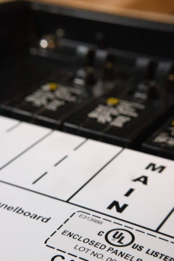
THIS is how you will receive your power distribution panel:
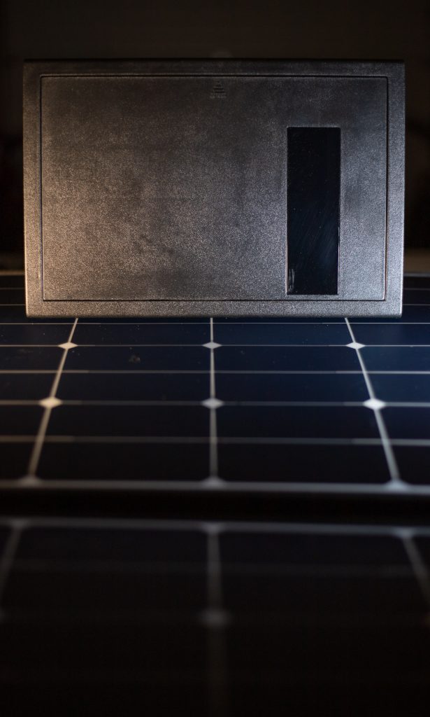
It’s got a black flip-down cover on the front…
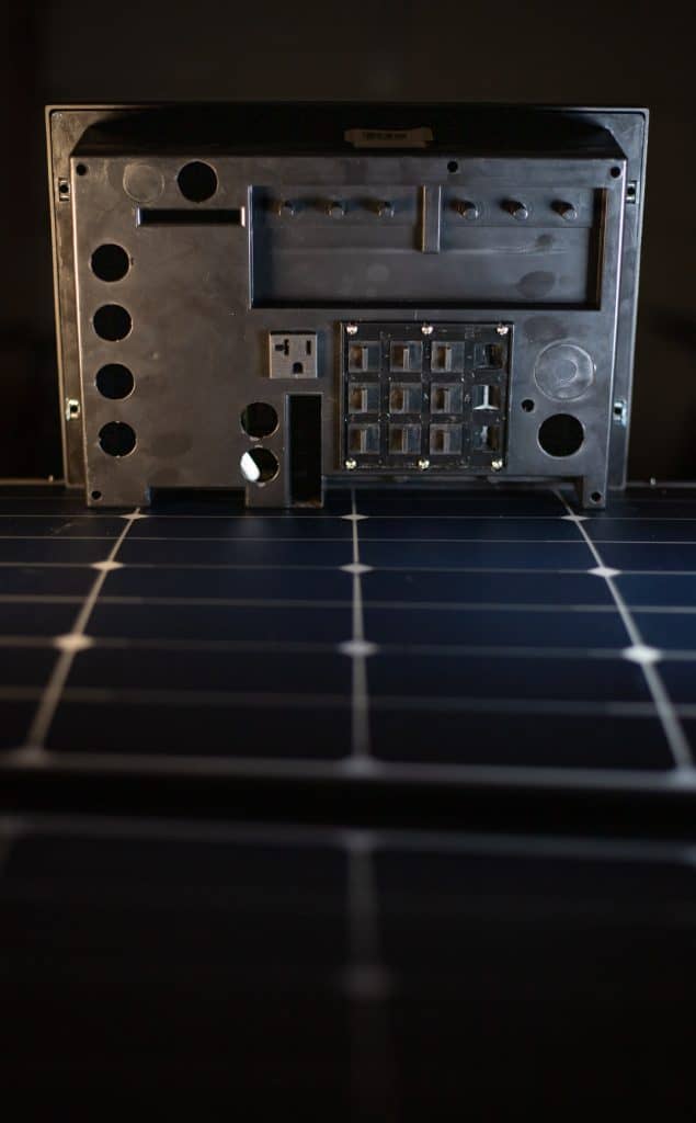
…and wire access knockouts in the back:
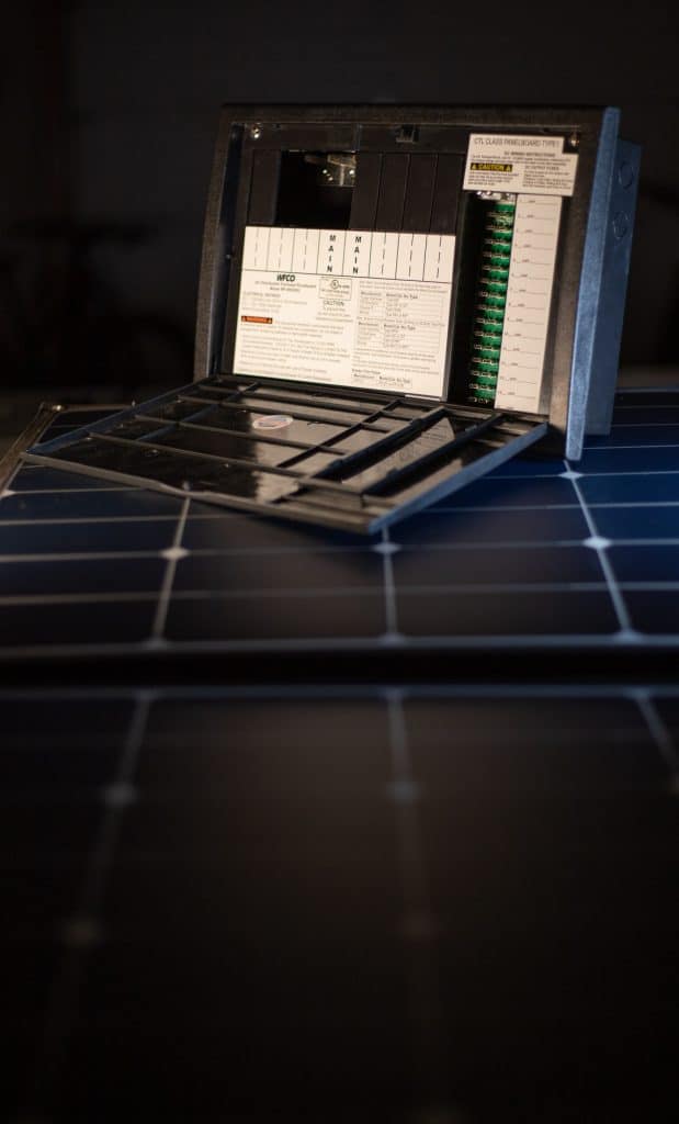
Lower the door on the front and you’ll have access to where your AC breakers and DC fuses will be.
A SLIGHT bend of the door will remove it from the box
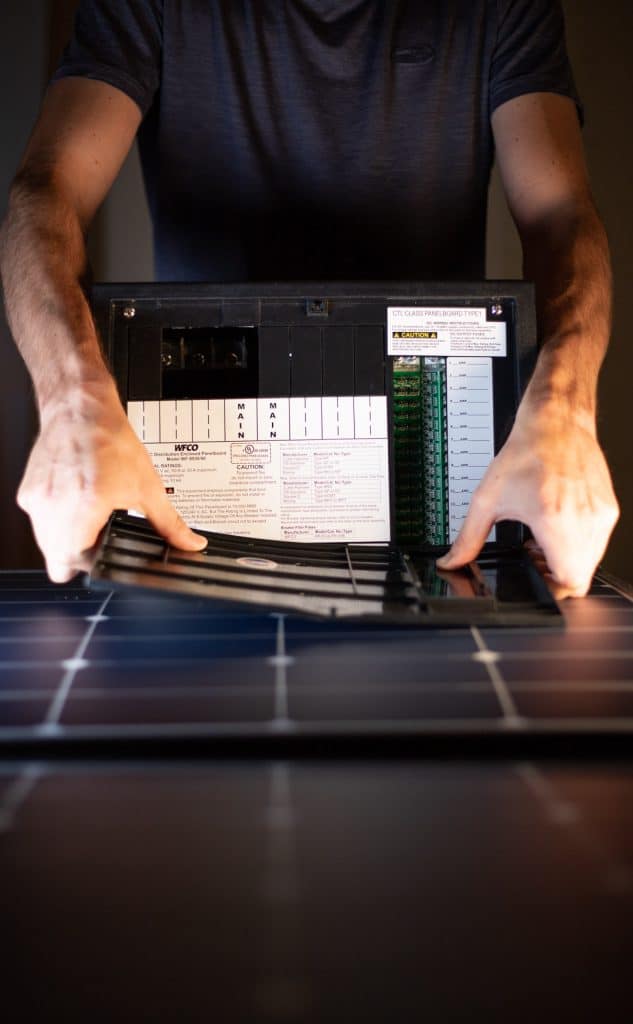
Remove these 4 screws around the corners to remove the trim ring.
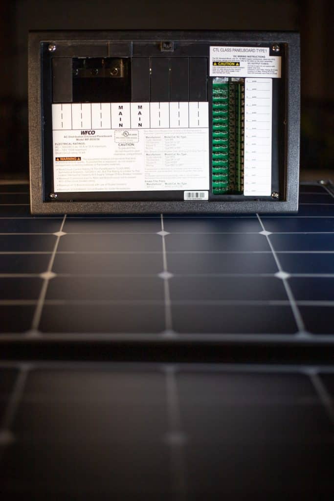
This power distribution panel is designed to be mounted in a 12 ¼ x 8 ½ rectangular hole. For this demo, I’m not actually installing this in a van, so what you’re seeing in these pictures is just a mock-up.
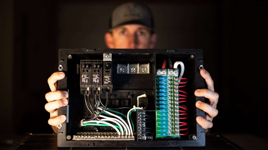
The right side of the box is designated for the DC side of your system. This will be powered directly from your battery or battery busbar.
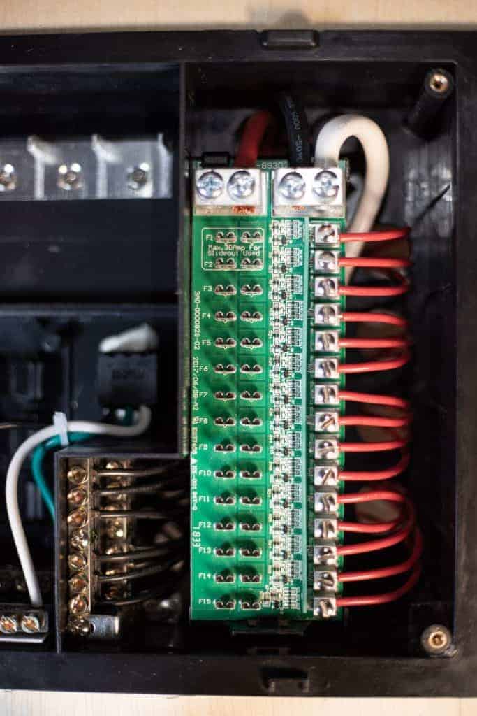
The left side of the box is designated for the AC side of your system. This will be powered from the AC output side of your Inverter. Here’s a shot of the final wired product:

If you’ve got a Pinterest Camper Van inspiration board rolling, that picture would be a good one to pin, don’t you think? Okay, So… Let’s start with wiring the DC side of this box.
Wiring the 12V DC Side of the Distribution Panel
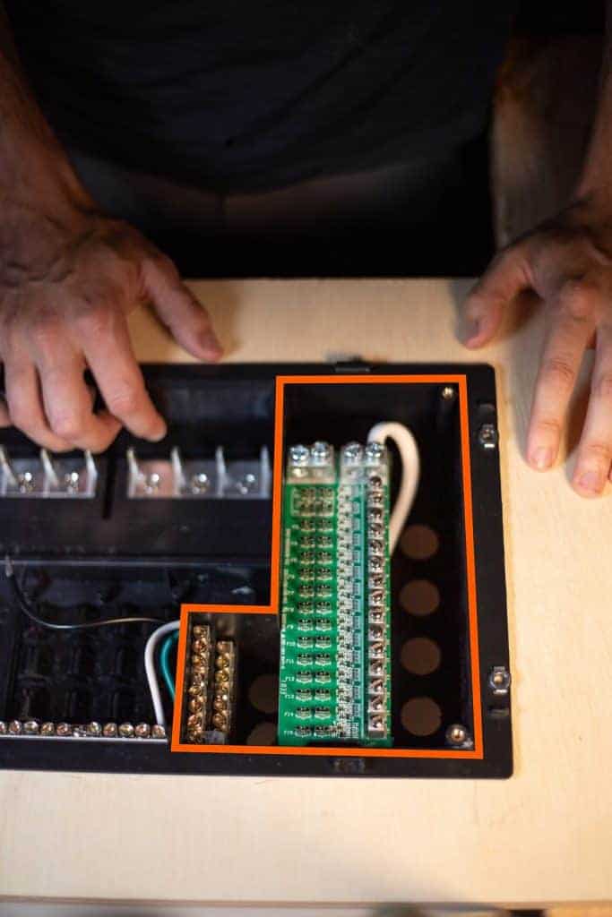
Knock out three or four of the plastic knock-outs on the back of the box with a screwdriver and bring your Positive and Negative wires from the battery into the box. (Please disconnect power to these wires before working with them).
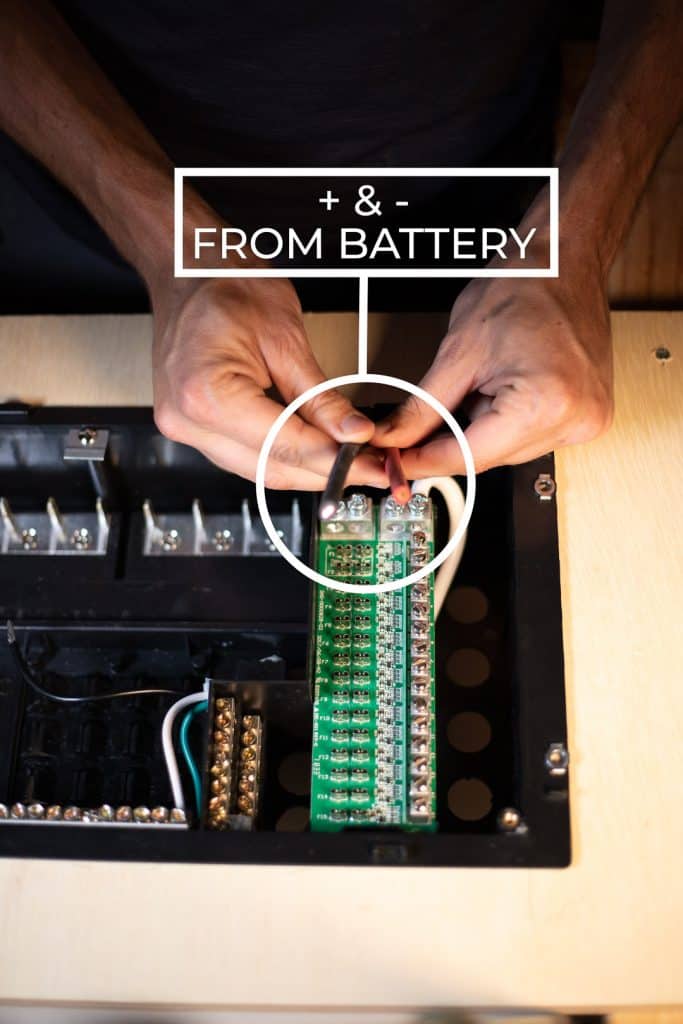
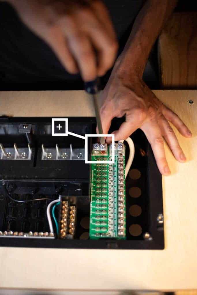
There are two big screw lugs at the top of this circuit board; your positive wire will go to the left lug.
…and your negative wire will go to the right lug.
Now, if you were to reconnect power from the battery, you’d have power coming into the DC distribution panel and have power at ALL of these fuse holders.
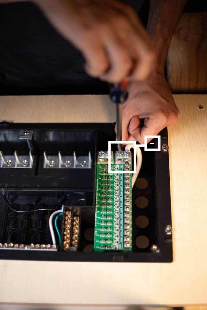
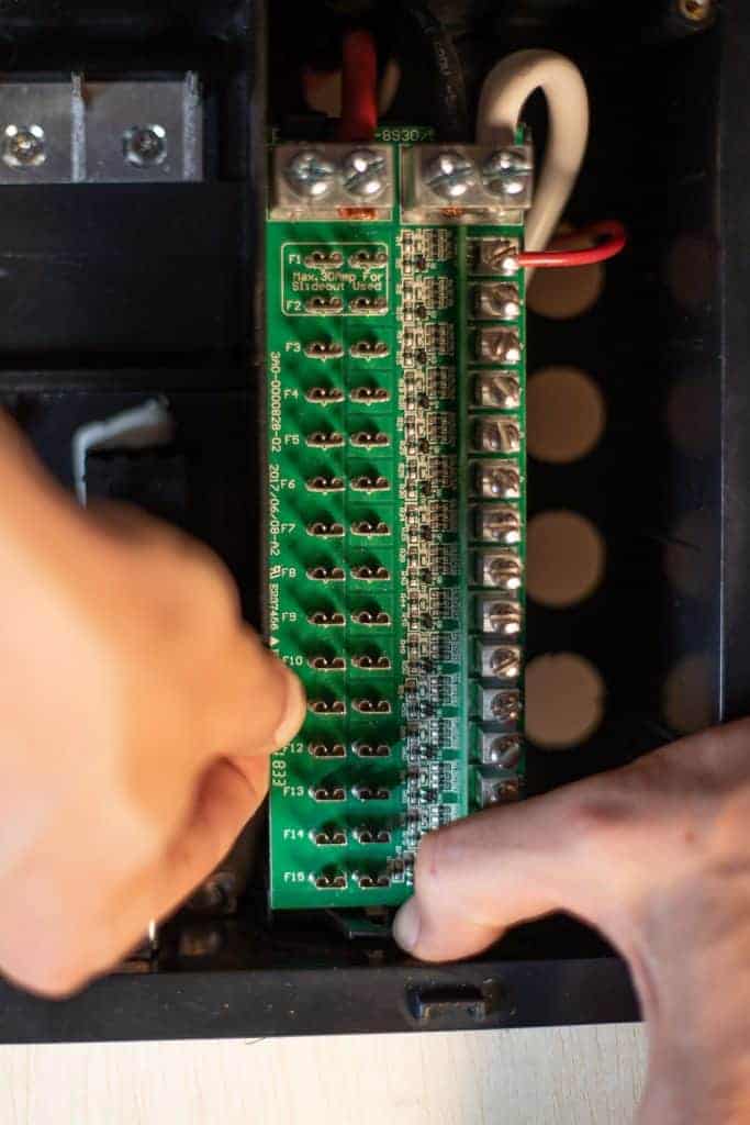
Now, when you’re ready to start running the wires for your 12v appliances, all you’ll have to do is bring your duplex wire into the box from the back and attach the positive wire to any of these lugs here:
I recommend starting at the top. Simply strip a quarter inch from your wire, loosen the screw, insert the stripped wire, and re-tighten the screw. Give the wire a little tug to make sure it’s secure.
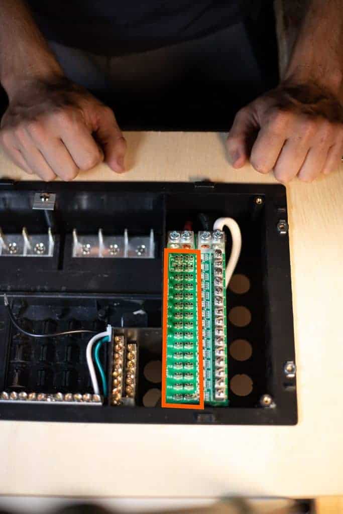
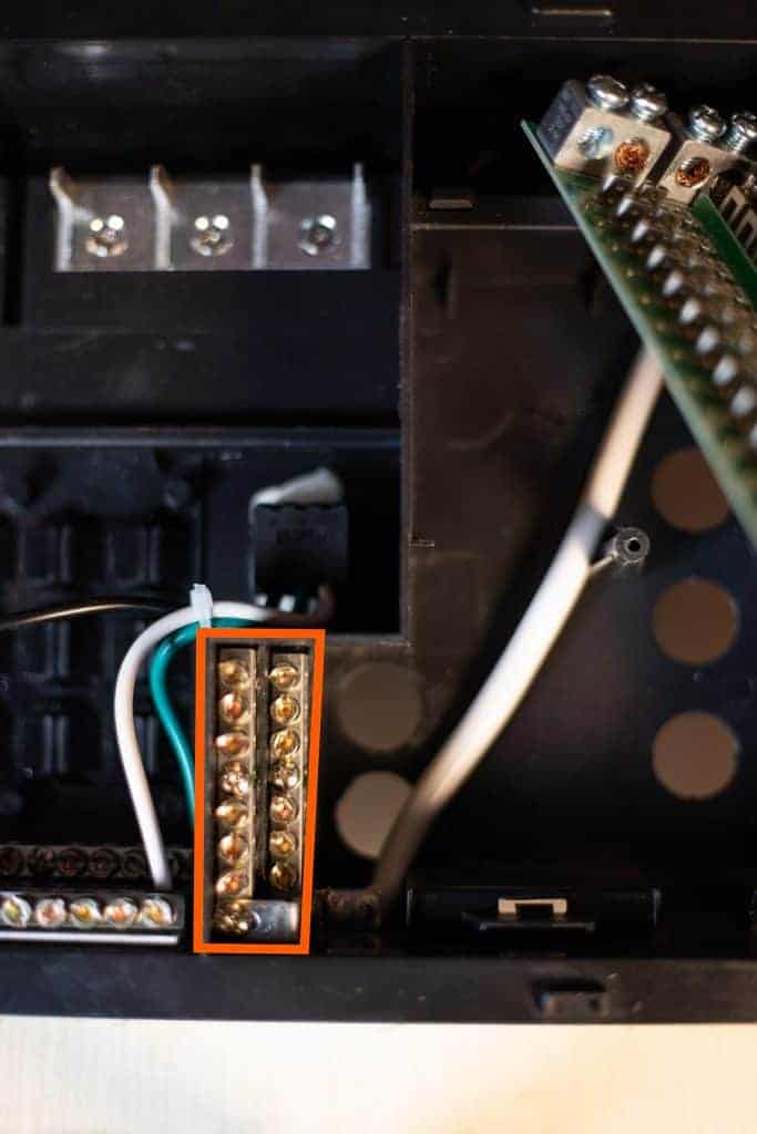
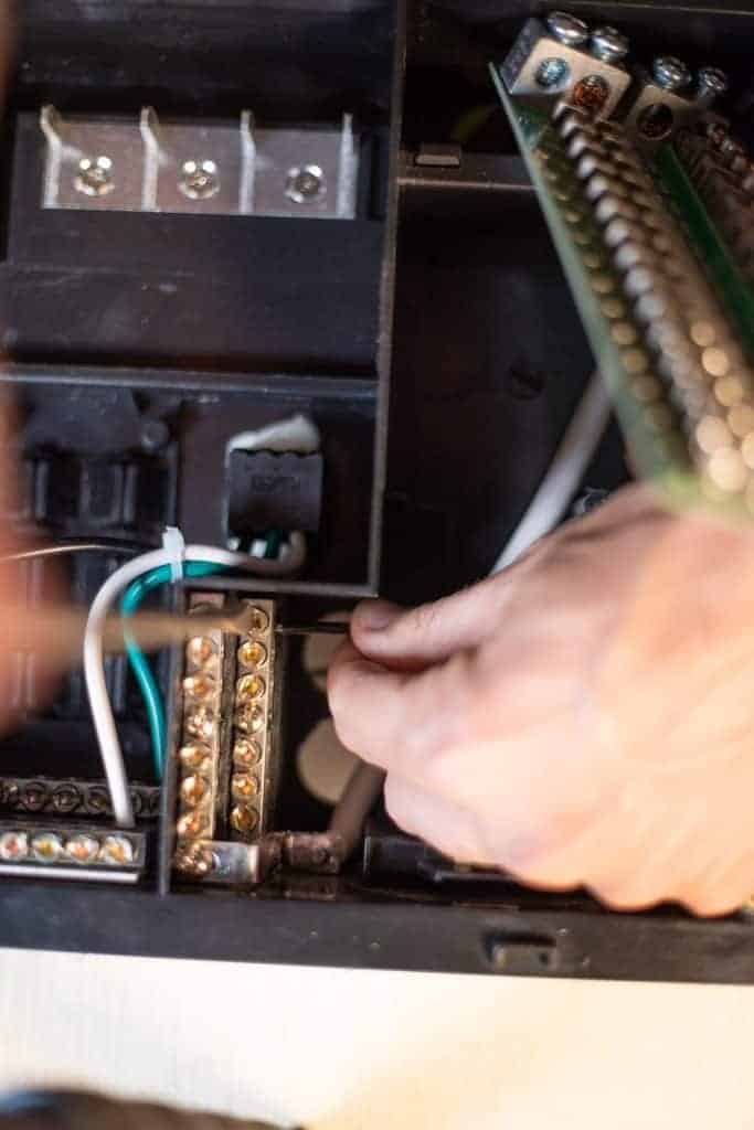
There is a clip on this board that if you pull it toward the bottom of the box, it will release the circuit board and move it out of the way so you can access the negative busbar easier.
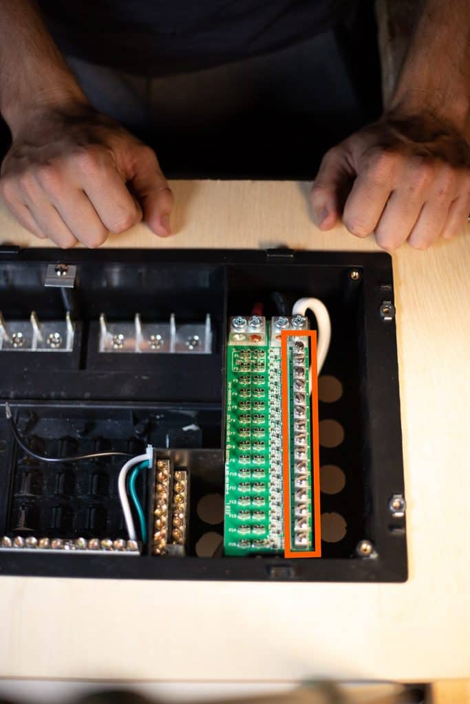
The negative wires from the duplex wire you just ran will go down to this negative busbar and attach in the same matter under these screws.
Strip a quarter inch from your wire, loosen the screw, insert the stripped wire, and re-tighten the screw. Give the wire a little tug to make sure it’s secure.
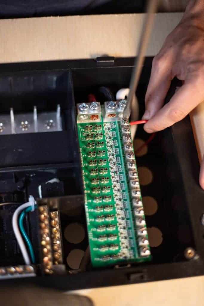
Repeat this process until you’ve added all of the 12v circuits you need and re-clip the circuit board back to the box:
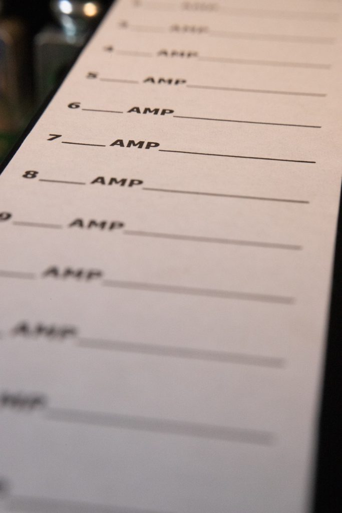
Keep track of what wires go to what appliances as there is a label on the distribution panel trim ring where you’ll want to make note of which fuse is which.
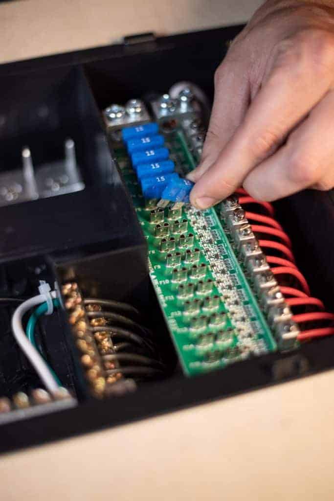
Now you can insert your spade fuses into their respective slots.
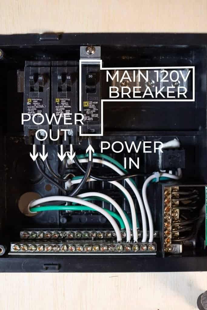
On the AC Side of the box, you’ve got 3 different busbars. The Bottom two are Neutral and ground with the ground in the back and the neutral in the front. Up top is the positive breaker busbar.
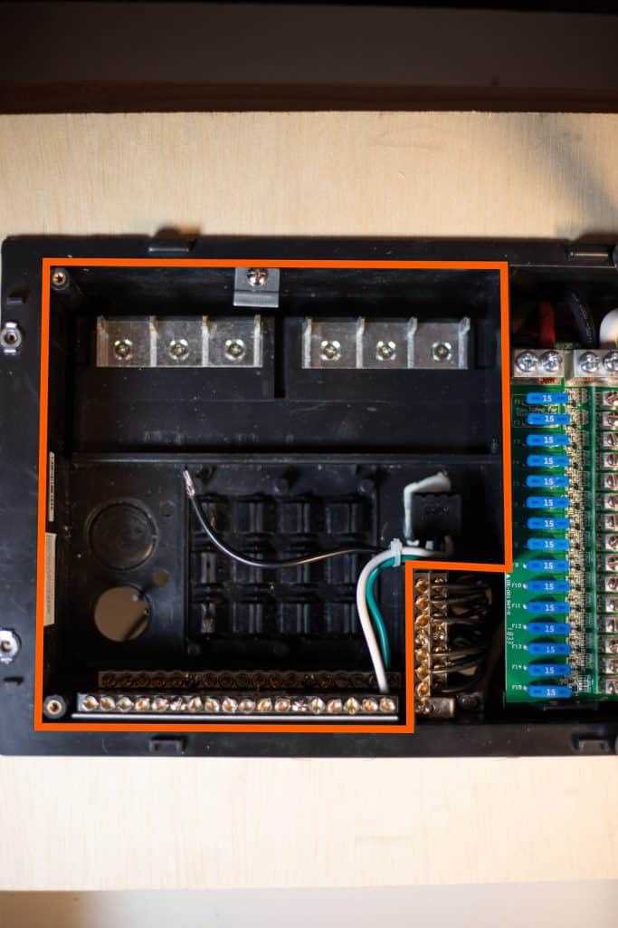
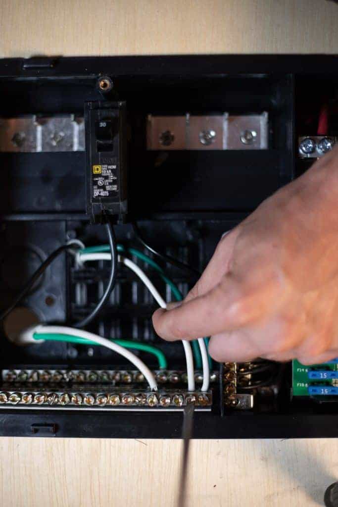
Making sure there is NO power coming from your inverter, bring in the 3 conductor wire from your inverter’s AC out into the distribution box via the knockouts on the back. Cut the sheath of this wire about 4-6” and strip back a half inch of insulation off of each wire. The Green goes to the Ground busbar…
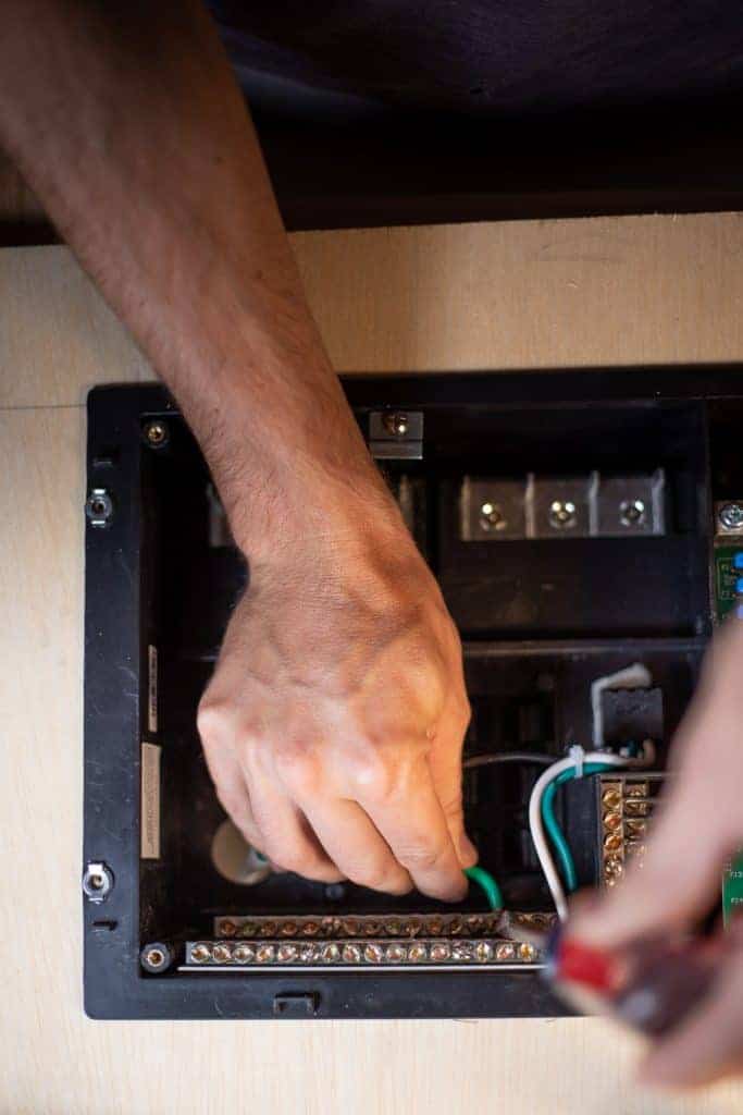
…and the White goes to the Neutral Busbar.
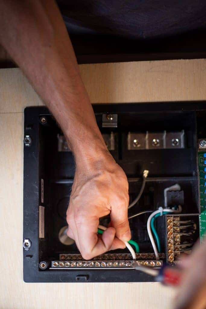
There’s already a 120v plug built into the back of the box and the green and white wires should already be connected up to their respective busbars.
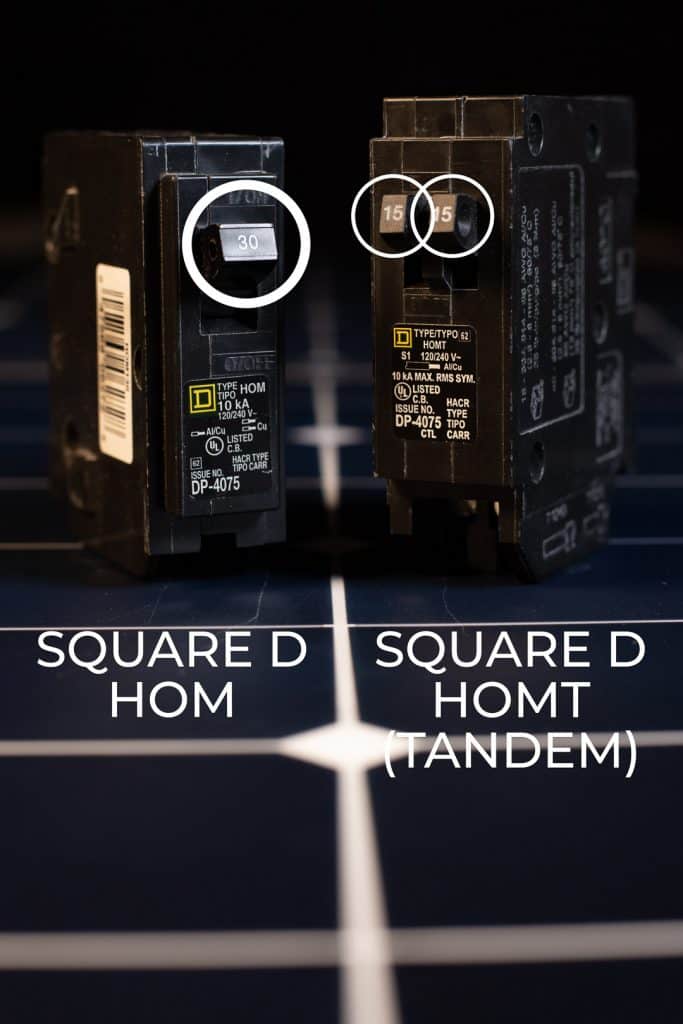
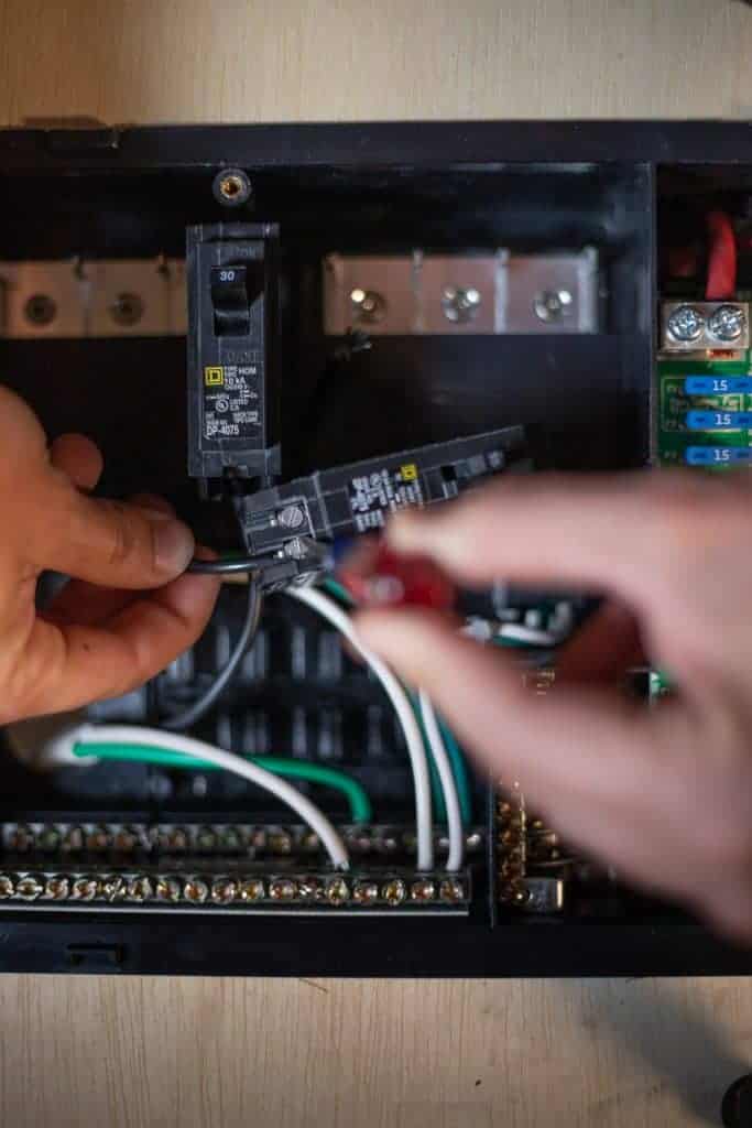
Now you need your AC breaker. There are a few different types of breakers that will work with this box, but I’m using Square D Home and Square D Home Tandem breakers.
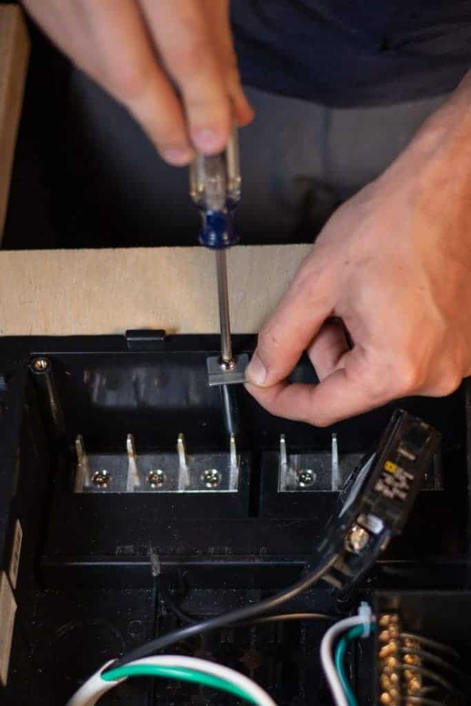
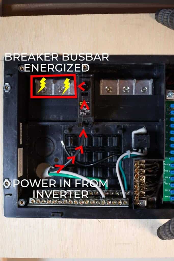
For the breaker coming from the inverter into the box is the single-pole HOM breaker. There is a screw on the bottom of it. Loosen that screw, insert the black wire under the washer, and retighten the screw. Give the wire a tug to make sure it’s secure.

Remove this screw and retaining clip and set aside.
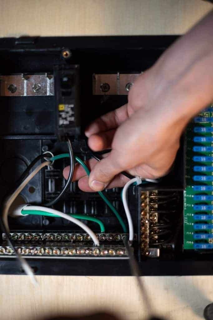
Clip the bottom of the breaker onto the bottom rail of the box…
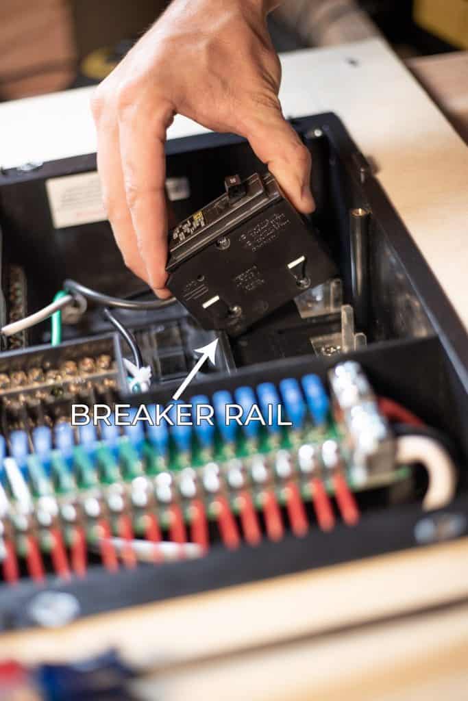
…then tilt (push) the breaker up so that the positive breaker busbar spline goes into the slot of the middle of the back of the breaker.
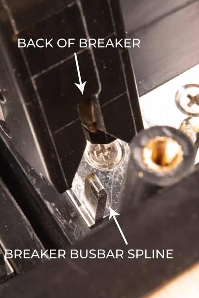
Now, if you had power to this wire and turned on this breaker, this whole positive breaker bus bar would be energized:
Next, I’m going to show you how to add a breaker so that you can run a wire out to your various 120v AC appliances and outlets.
Bring in your wire that will run to those 120v appliances or outlets. Strip back 4-6” of sheathing and strip the insulation off the last ½” of wire. The Green goes to the ground busbar…
…and the white goes to the neutral busbar.
Then you’re going to grab your Square D HOME Tandem Breaker.
This is a space-saving breaker allowing you to have two (Tandem, right?) circuits on only one breaker busbar space.
Loosen one of the screws on the bottom of this breaker. Insert the black wire under the washer under the screw, and tighten the screw down. Tug on the wire to make sure it’s secure:
Fix the breaker to the box in the same way you did the last breaker. Clip the bottom of the breaker to the rail and tilt up into place with the breaker busbar spline going into the middle of the back of the breaker:
Repeat this process for as many 120V AC Circuits as you plan on having.
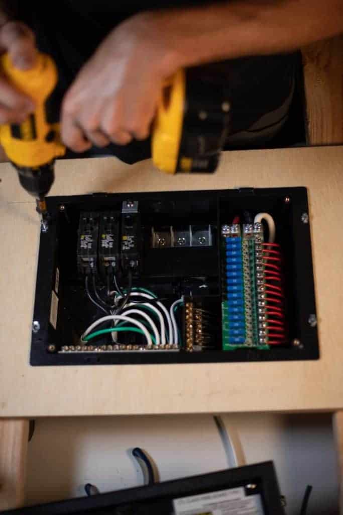
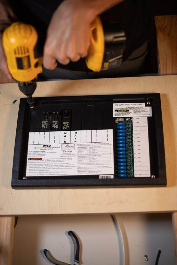
Now you can insert screws into the box to hold it to your cabinet or wherever you are mounting this:
Reinstall the trim ring starting with the top 2 screws:
…and reinstall the door:
Now, if you haven’t done it already, now would also be a good time to label the various fuses and breakers for what they go to.
Flip on the AC breakers and reconnect your DC wires to your battery and you should have power. That’s all there is to it!
If you have any questions about this project, leave them in the comments below and I’ll get to them as soon as I can. If you found this helpful, it’d truly mean the world to me if you’d share it with somebody or a group who you think could benefit from it.

111 Responses
Just recently had your channel recommended to me by a friend and I am loving your careful presentation style and feel like things are starting to make sense. I am working on building an electrical system for a boat, but its all the same components, and you seem to be following ABYC practices. But one. And I am wondering why not. I understand that ABYC recommends that for DC wiring that the negative or ground wire be yellow instead of black, because, just like in vans, 120v wires use black for ground so to avoid any chance of a mistake between AC and DC negative they recommend the different color. Why is this not standard practice in all boats and RVs?
Yellow wire isn’t very readily available to the consumer market, which is why I don’t put it in my diagrams or anything.
The plug that comes built onto the ac side of the panel, the white and green are plugged in from the get go, but the black is free floating in the beginning photos. You never said what to do with the black, but eventually it looks like it’s plugged in later in the photos.. where does it actually go? Thanks!
To one of the breakers, the same as any other circuit.
Hi Nate
Thx so much in advance for helping us all with our questions!:
Mine are:
1. on the new progressive dynamics 18 slot DC panel that you recommend to replace the old WFCO AC DC panel I notice in the description that it says to use copper wire only. Does this include multi- strand wire (which is what I have used in our van to help make it safer)?
2. Assuming yes, is there a limit to the gauge multi strand wire that the terminals in the panel can take? Eg will it take say 6 down to 14?
3. Is it best to use a ferrule and if so which do you recommend for this progressive panel?
Switching to the separate AC panel:
1. Same questions as above
2. If I am pulling my AC from the 120V output of a GoalZero yeti1500x directly into the panel, do I need to separately ground the ground terminal on the panel to say some bare metal on the van?
Thank-you!
1: Yes, stranded copper wire is still perfect.
2: 10 AWG is the biggest it will take. 16 AWG is the smallest you should use for a DC circuit.
3: Ferrules do indeed work well for this panel.
1: Correct
2: We don’t have any systems at https://www.explorist.life/solarwiringdiagrams with a Goal Zero unit and I shouldn’t advise on a system I didn’t design, so I must decline to answer this one.
Very helpful. Thank you. I’m currently replacing a Jensen RV stereo in my class B+/C with an Alpine car stereo. (The installation is in the coach, not the chassis.) After a conversation with Crutchfield support, it looks like I need to run a second 12v+ power supply wire from the battery/distribution panel to the stereo. Do I need to have a corresponding negative wire as described in your article or will using the existing ground in the stereo compartment work? Thank you.
If your house battery bank is connected to a chassis ground, the existing ground should work fine.
Hi, Nate,
For the black wire to the outlet on the back of the panel, did you use a dedicated half of a tandem breaker?
Yes. If you don’t think that outlet will be useful, you don’t have to wire it up. I generally just use it for temporary power for system testing and then disconnect it to hook up an actually useful circuit.
Hey Nate! I have everything wired to my distribution panel, but when I go to connect it back to my battery I get BIG sparks from the negative terminal. Sparks so big that they partially melted a wire connector. I’m connecting (+) first and then (-).
Any ideas on why I can’t properly connect the distribution panel to my battery bank?
Goodness! Sounds like there is a direct short somewhere (which means you’ve probably got a positive and negative wire touching somewhere).
Hi Nate, thanks for creating these great resources. I’ve read through all the comments but still have a couple of questions about the panel AC right side.
Assuming I want to use AC Out 2 from the Victron multiplus 3000 to have shore power only circuits, can I simply run a second 6/3 cable from Out 2 and add a second 50A breaker to the right side?
No issues with the common neutral bar?
Can the breakers be two separate 50A or would this require a double pole 50A for any reason?
Thanks!
You can definitely do that. The breaker would indeed need to be dual pole. There is no problem with the shared neutral because the Multiplus simply passes that through on the same phase as shore power.
Is this the same for an existing/prewired RV?
I disconnect and remove my existing converter?
Generally yes. Just disconnect the wires, both AC and DC, that connect the converter to the 12V fuse block and the AC breaker box to disable the converter.
Nate, thank you for the video! I do have a question though. Do I need to run the GROUND from AC side Ground busbar to a frame?
Not if connected to an Inverter/Charger with a ground relay like all of the ones at https://www.explorist.life/solarwiringdiagrams
Nate, you are most effective.
Thanks!
Glad it helps!
got a question about wiring, please refer to your wiring diagram
in the diagram, the shore power (comes off the grid via standard extension cord) is wired into the 2000W inverter
i have a 1000W inverter, which does not have an AC input
can i wire the AC input line directly into the AC side of the distribution box, and also run an AC line from the inverter into that same box?
i understand that the AC shore power line won’t charge my battery that way, but we could use it for the few other AC applications we’ll have
thanks in advance
For that, you should use a transfer switch: https://amzn.to/2Z34bQB
AC Input Primary = Shore Power
AC Input Secondary = Inverter
Output to AC Breaker Box
@Nate Yarbrough, thank you, sir, appreciate all your help!
What inventor did you use that has pos grd and neutral.all the inventors I see have only pos and grd.how would I wire a neutral to the box?
Every inverter I have in each of my recommended setups at https://www.explorist.life/solarwiringdiagrams has a hot, neutral, and ground output.
Hey Nate, am I to understand that one main AC breaker will charge three of the breaker channels? If so, what is required to install a second main breaker to charge the entire bar?
When using tandem breaker (Labeled as: “HOMT” https://amzn.to/2Nnk9Cp), one side of the breaker box can handle 6 circuits, which is plenty for a camper. Charging the other side of the breaker box requires a 50A 120V/240V shore power setup which is overkill unless you are trying to power something that needs 240V (which you would need a totally different breaker box anyway) or two air conditioners.
Hi Nate,
Your tutorials have really helped me with understanding and tackling my wiring, so thank you!
I have 2 questions:
When wiring for a 12v USB plug (or 110V) with 2 outlets on a single wire, do you run a wire / fuse according to the total amps that would be used if both USB’s are in use at the same time? For example 1st USB port is 1.2V and second USB port is 2.1V so total voltage when both in use is 3.3V.
Second, I am trying to find the best conduit for running wires – do you suggest the Carlon “Smurf Tube” is good for both 12V and 110V wiring? Any other suggestions?
Thank you!
Jack
For USB outlets, it’s best to use the watts of the USB outlet and divide that by the battery bank voltage to get the amps @ 12V being delivered from the distribution panel to the USB outlet to do the wire size calculations there. The voltage is being lowered to 2.1 or 1.2v from 12V at the usb outlet itself.
Hello Nate, In my conversion i am only going to need AC for maybe 3 outlets(phones, computers, etc.) in the van. Would i hook up all my outlets to one breaker or each on their own?
OR my original thought was to use a more simple fuse in-between the inverter and outlets? And DC would be separate.
Your input would be greatly appreciated, Thank you for sharing such informative videos for so many to go off of!
Here are my recommendations for witing 120V Circuits: https://www.explorist.life/how-to-wire-120v-ac-circuits-in-a-diy-camper-van/
Awesome video and blog post! Quick question… my 2000W inverter has two AC outputs. Do I use just one as an input to the panel? Is there a way to use both?
If available… I recommend using the hard wired option. On most inverters, this will allow you to use the full capacity of it’s shore power passthrough.
Hello! Very helpful, thankyou, we love your stuff! When wiring a breaker/fuse box combo such as this – what if we are not installing solar, and so dont have power coming into it from a battery? Where does the power come from? How do you wire that?
Thankyou!
With no solar and no battery, this likely also means no Inverter… So if you are ONLY operating from shore power, you would be using AC directly from shore power but to power 12v appliances & such (if used) you would want to buy a power distribution center with a ‘converter’ in it, which would convert 120V AC power to 12V DC power to power the 12v fuse block. Here is one of those units: https://amzn.to/3n0Osff
@Nate Yarbrough, I just found this and really appreciate the clarity of the info. Sorry if I missed this, but how would you energize the second AC bar if you wanted to add more circuits on that side?
Thanks again for the great info!
There is no easy way to accomplish that. But 6 circuits in a camper van should be more than enough for anybody. See an example of a full 120V branch circuit system in 6 circuits or less here: https://www.explorist.life/how-to-wire-120v-ac-circuits-in-a-diy-camper-van/
Your explanation about everything makes it easier to do. Well done. Thank you.
Nate, in this video and blog you suggest that the power come from the Inverter to the electrical distribution panel. Should my shore power go through my 1000W PSW Inverter, or can it go directly to my distribution panel? I have the WFCO 8735 panel. Thanks
Nate – love your videos! Not until watching this did I realize that for my AC outlets I need 12/3 wire. I already ran 12/2 wire. Do I need to run new wire, or is there a way I can still use the 12/2?
120v Circuits need 3 conductor wire. Hot, Neutral, and ground. If you ran wire with only two conductors… you’ll unfortunately need to redo it. More info: https://www.explorist.life/how-to-wire-120v-ac-circuits-in-a-diy-camper-van/
@Nate Yarbrough, ok, thanks man! Appreciate the advice.
Hey! What do I do if the fridge wire I am trying to use doesn’t fit into the bus bar holes? I have an 8 gauge wire and I am not sure if there is a connector or an adapter that can bring the width down to fit into the bus bar holes.
There’s really not a good way to connect that inside of the power distribution center. An external fuse (connected to your Lynx Distributor or Busbar) or running with 10 AWG wire are really the only two options there.
Hey Nate,
Great post! Really liking your methods. I have a DC fridge that requires a 6 AWG wire and a 40A fuse. Does this panel support that wire size on the DC side? I just want to be sure I will be able to get a clean and solid connection to the fuse box. Thanks again for the post!
Nope. This fuse block has a, I believe, 10 AWG max wire size for the DC branch circuits.
It it possible to connect the AC side of this panel to the AC out on he Jackery? and the DC side of this panel to the DC out on the Jackery? If so what wires/connectors would you recommend?
Also thinking about a TS 30 transfer switch to switch between shore and jackery.
Thanks.
Although quite overkill; it could be wired like that. I don’t have a wiring diagram & parts list available that shows how to do that, so you are going to have to do your due diligence and spec that out yourself.
Thanks for the great info , my question is; should the main breaker always match the amperage of the supply plug, if l have a 30amp 125volt plug
I should have a 30amp main breaker. This is true even though there are 4 or 5 breakers adding up to more than 30 amps ?
Usually, but not always. Can you share more about your project and I can give a better example?
Hi Nate, is It okay to connect the 6 awg battery wires coming from the distribution panel straight to the batteries and would I need a fuse in between? In your diagrams it shows them going somewhere else. Thank you!
You would indeed need a fuse as shown in the following diagram: https://www.explorist.life/3000w-inverter-400-600ah-400-to-1200w-solar-camper-solar-kit
What guage wire are you running from battery to panel?
You can see wire sizes on any of the diagrams found here: https://www.explorist.life/solarwiringdiagrams
happy customer and thousands of views later, i’m finally doing this after planning for a year. Thanks Nate. I only have two of the tandem breakers based off the “200ah 525w” wiring diagram. I want to run 6 outlets, can I have two outlets on one breaker? as long as the loads are small. I’m doing simple computer speaker type stuff, nothing heavy load. I think the combined amperage would not trigger the breaker, so I’m fine right?
Thanks
Tim
You can have as many outlets as you like on one breaker. Think of your house… you may have 6 outlets in your bedroom all connected to one breaker. If you connect a space heater to each outlet, you will trip the breaker for that circuit. It’s the exact same principle for your camper.
Hi Nate, is there any reason I couldn’t use this box for 15a service? Obviously I would need to limit my breakers/simultaneous usage, but from a connectivity and functionality perspective it should work fine correct?
Yes. Consider wiring like I show in my diagrams are get a 15A to 30A RV adapter: https://amzn.to/3hecAY9
Nate, all of your content is so helpful. Thank you. If you have time, I’d love to get your thoughts about this: I am using this WFCO distribution panel. I have 30A 120VAC coming from my Xantrex FC 2000W inverter over 6/3 wire. I have 8 branch circuits, all of them either 15A or 20A. I am using QT breakers for all of the branches. I would like to connect the 2 hot bus bars so that I have space for all of the branches, but I only have 1 hot wire. My plan is to use a 30A double pole breaker to straddle between the bus bars and short the 2 hot inputs to effectively connect the 2 circuits. Do have a better idea?
I don’t know that the box can be set up like that. You may reach out to the manufacturer for that info. My recommendation would be to pair down the number of circuits used so there is a max of 6 circuits.
Nate,
I’m considering a cargo trailer conversion, no solar, dc power, and ac power through shore power connection.
How about if I use this panel:
https://www.amazon.com/Arterra-0318-1454-WF-8955-PEC-Converter-Charger/dp/B004BC9ABS
That way I can charge batteries through converter/ shore power?
Your build has inspired me.
Comments?
I suppose that would be fine, but I can’t say for sure as I don’t know anything about the rest of your system/components so you’ll have to do your due diligence. That panel won’t work with any of the diagrams at https://www.explorist.life/solarwiringdiagrams
Best go-to source for RV / Camper / Van Conversion wiring!
I appreciate that!
We have converted 4 buses, several rvs, other projects and vans. In our 70’s, this current Ford transit is our last, we hope.
We’ve installed a cheap set of ceiling pucks, then replaced with a better quality set…..same results. We have “glow” after switching off. These lights are on two seperate, fused, runs.
What, “exactly”, can we do to correct? (I have ordered a small pkg of 1/4w resistors, which seem necessary to my fix, but have no idea what to do with them, since our puck lights are not a “bulb” type LED – or if they are really my answer)
Much thanks, Deb
It sounds like the switch may be bad. That’s where I would start.
Hey Nate,
In looking at the wiring diagram for my system (200 amp hour BB lithium with 400 watts of renogy) I see you connect the inverter (AIMS 2000w) to the AC side with a three wire. But I all see both a red + and black – coming from their respective bus bars and into the distribution panel. Where do these two 6 AWG wires go in the distribution panel?
Thanks, Greg
Okay, my bad-watched your video and they are obviously the dc power supply. DUH! I am starting to wire this in the next day or so and am a little antsy trying to figure everything out. That’s for helping to steer me in the right direction. Any chance during tutorials you can have no music?
Good! Glad you figured it out. No can do on the videos with no music. Sorry. I’ve done that in the past and people actually watch my videos more/longer when there is background music covering up fan/furnace/random background noises. I have analytics in Youtube that tell me this. 🙂
Those go to the DC side of the power distribution panel.
Nate…thanks for the helpful info. Your video explains how to wire the inverter to power the distribution panel, but I am confused on how to also wire the panel for shore power as well. How do you wire the AC side so that you have both inverter power and shore power to the panel? Thanks in advance.
If you are using an inverter charger like shown in all of the diagrams at https://www.explorist.life/solarwiringdiagrams the shore power comes into the inverter charger and will pass through on to the Distribution panel.
Hey Nate,
If I’m looking at this distribution panel correctly, there are 15 spaces on the DC positive bus bar but only 12 spaces on the negative. If I am hooking up 13 sets of wires, should I connect two different negative wires to the same slot on the bus bar? Is there any problem in doing that?
As long as the wires fit in the busbar hole nice and neat, there is no problem with that.
You failed to discuss the proper bonding of the panel to the vehicle frame.
That is covered in all of my wiring diagrams at https://www.explorist.life/solarwiringdiagrams. Bonding of the AC side of the system is taken care of through the Inverter/Charger.
Hey Nate! I couldn’t find any info about wiring ac breakers out to outlets and how to properly size the fuses and wires. I’ve checked out your wiring and fuse calculator but wasn’t sure if this also worked for 120. Thanks in advance!
For standard household outlets, you’ll use 12 AWG Triplex wire protected by a 20 amp breaker. For bigger loads like an air conditioner or water heater you’ll likely use 10 AWG Triplex wire protected by a 30 amp breaker. That’s pretty much all. AC wire sizes are much easier than DC wire sizes.
@Nate Yarbrough, Thank you! I came digging through the comments hoping someone else had asked this. As always, so so helpful!
Nate,
What to do when using a solar generator?
1. Use Goal Zero Yerti 1400 or 3000 as power source (shore, DC, solar) or similar solar generator
2. I get the 120v AC Yeti outlet to breaker box 120v
3. How do I wire the Yeti (or similar) to breaker box 12v DC?
Thanks in advance,
Frank
I wouldn’t use the 120V side of the AC breaker box as the yeti already has breakers built in. I would simply use the DC output side of the Yeti to power something like the Blue Sea Fuse Block.
Hi Nate, your information is great and you explain it well in your videos. So I have watched some other people designing systems on youtube and you seem to be the only one with a master shut off switch, the red square in your diagrams near positive busbar. What is its precise function, and safety concerns without having one. Thanks Chris
The master shut off switch just allows you to disconnect all of the loads while still allowing the solar panels to charge the batteries in the case of storage. No real safety concerns either way. More of a convenience thing.
Hi Nate,
Are you able to use only the AC portion of this distribution panel?
Based on your description, the AC side gets its power from the inverter being plugged into the main breaker. Would not having the Positive and Negative on the DC side prevent the AC side from working? or is it completely separate?
Thanks. Your blog is super helpful.
This box has both AC and DC all in the same box. The wiring between the two is totally separate, they are just both housed in the same box.
Hey Nate!
Thank you for all the info. Just quick question. Why did you chose a 30a breaker for the panel? Basically I’m asking how to size my panel. I have 4 15a outlets that’s it. Thanks in advanced!
The breaker is determined by the size of the wire it is attached to. For AC circuits: 6 gauge = 50A breaker, 10 gauge = 30A breaker, 12 gauge = 20A Breaker.
Hello,
Thanks for all the great info. Do you have a post about combining solar and shore power into one cohesive system?
All of the wiring diagrams found at https://www.explorist.life/solarwiringdiagrams accomplish just that. I won’t produce a wiring diagram that doesn’t include both of those charging methods.
Hey Nate!
I’m having a lot of trouble figuring out the fuse sizes that are to be inserted the DC side. I see here that you’ve used all 15amp fuse blades. I understand that there are calculations to be made for each appliance that you’re powering from the DC side, but I’ve read that there are also restrictions for the fuse size based on the wire size your running to each DC powered item. For example, I’ve read that 16awg would have a limit of 7.4A, implying that you should not use a fuse that exceeds that number. Do you have any insight you could share about how you went about assigning fuse sizes on your DC side? Thanks so much!
Evan
Sure! You should first check out my wire size calculator because it will make not only wire size recommendations, but also fuse size recommendations as well: https://www.explorist.life/wire-sizing-calculator/
And for a bit more back-story on how this calculator works: https://www.youtube.com/watch?v=ki3WXVR48eM
Hey Nate,
This is awesome!! Question on AC wiring. Where would you recommend getting the 3 conductor wire? I’ve had trouble finding the red black green type you used.
Hey Steve! You’d be looking for 10/3 or 12/3 ‘triplex’ wire. I’ve got a page here where I source all of my wire from: https://www.amazon.com/shop/exploristlife?listId=2M24K4BLC33U7 The triplex wire is at the bottom and is the 3 conductor you were looking for.
Hey Nate! Awesome video and blog post! Currently in the middle of my build and curious.. Can I use the 20 amp receptacle to power the AC side? I have a male to male 3 prong 2 ft cord that would fit nicely from my AIMS 2000w inverter to my WFCO distribution panel. Is this possible?
Nope. That’s definitely not advised. Male to Male cords are incredibly dangerous. I’d highly advise cutting it in half and just using the cut end as the end you wire into the panel as I’ve described in this blog post and then plugging the other end into the inverter (if you’re trying to avoid hardwiring into the inverter).
Comparing the old diagram you posted a while back and this one. Would you still need the busbars in addition to what’s provided here in the all in one set up?
I’m not sure I fully comprehend your question, but there is no crossover between the old and new diagrams. All of the parts on the new diagrams are necessary to wire it in the way depicted in the new diagrams.
I’d really love to see a video dealing with the wiring of a 50 amp service (say for a 5th Wheel) where an inverter/charger/auto transfer switch (like a Victron Multiplus 12/3000/120/50) is installed on one of the 50 amp lines. I’d specifically like to see how to disconnect the existing 50 amp lines, and then wire one, say the L1 circuit into the inverter, and then back to the distribution panel while reconnecting the L2 circuit wired to the power source as originally configured.
If you’ve already got such a video, could you please direct me to It?
Thanks for any help/direction you can provide. I want you to know that i’ve found many of your videos very helpful and informative and i’ll continue to watch (and learn) your future videos as they come out.
I’d very much like to do a video over that. In due time perhaps. 🙂
Why are you forcing me to use Google? The worst possible company in the world… WTF do they have to do with your spreadsheet? Why do I have to log in download your spreadsheet?
Please tell me how to continue to appreciate your website and blog without being completely turned off by your choice of browser.
I love your blog so far… please help!
I have no suggestions on how to make you like google more. It sounds like, perhaps, an internal struggle. Maybe this book will help: https://amzn.to/2Hi0rSN
You’re my hero
Thanks! 🙂
My hero too:) And I read that book. It’s PHENOMENAL:)
I do what I can. Haha!
Any suggestions for a full neutral bar? I have a power converter in my rv with 2 more spaces for breakers but a full neutral bar. Unfortunately cant seem to find a neutral bar with the same bolt holes to mount a one with a few more spots.
Some breaker boxes are rated for multiple wires under the same screw so you can check with the manufacturer to see if that is allowed.
The video and blog post doesn’t explain, or go into detail, the grounding and bonding of the system. You show the AC circuit grounds going to the AC side ground bar, and the DC circuit negatives going to the DC side negative busbar, but you don’t show the required bonding to the chassis, and whether the “negatives” and the “grounds” get bonded to the chassis?
Additional information on this would be appreciated. Thanks!
Hey Scott! That information can be seen on the overall wiring diagram page here: https://www.explorist.life/solarwiringdiagrams/
Thanks! Great tutorial
Awesome tutorial. Only suggestion I have is…can you add a button for us to download as a pdf in the near future. I can add these tutorial in a folder for future reference when I need to. Thank you so much for all you do to provide us valuable information.