
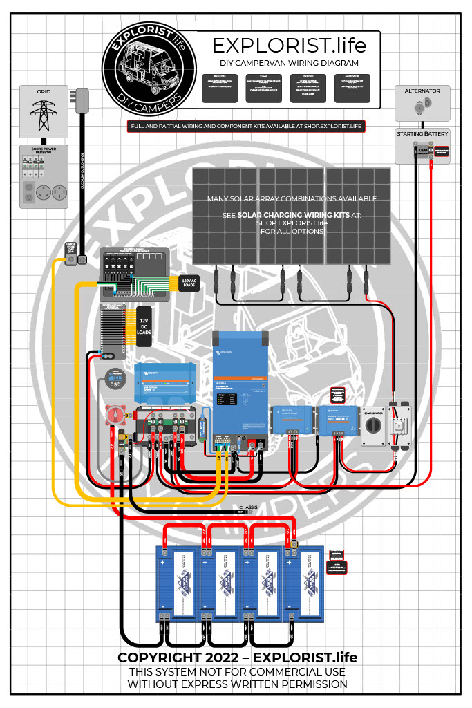
This DIY camper solar wiring diagram and parts list is perfect for ground-up electrical installs into campervans, skoolies, or expedition vehicles. This system is most suitable for systems that do not have a pre-existing house electrical system installed.
This diagram features:
- 2000W Inverter Charger
- 200+ Amp Hours of Battery Storage Capacity
- 200W-700W Solar Array Capacity
- Alternator Charging
- Shore Power Charging/Passthrough
Not quite what you are looking for? Check out other system setups here: https://www.explorist.life/solarwiringdiagrams
History of Changes to this Page (Click to Expand)
Changes Made Oct 15th, 2022: Added links and advertisement to purchase parts through the wiring kits at https://shop.explorist.life Keeping the parts list to amazon up to date has been a pain point, and by offering the parts (from the screws to the components) directly from us, we can keep up with our parts in stock and quality control. Also added separate AC and DC distribution panels to more accurately reflect currently available parts. Updated graphics to be easier to read. Wire/Fuse sizes did not change. Updated dual pole solar breaker to an actual solar isolator switch.
Post Published August 10, 2020
HOW TO USE THIS PAGE – VIDEO
This orientation video will show you how to best use this page to build your DIY Camper Solar Setup. It’s a quick watch but I think it’s pretty important.
DIY Camper Van Wiring Diagram
DIY Camper Solar Parts – Shopping List
The easiest way to purchase all of the parts needed for this wiring diagram is to purchase the:
And then purchase whatever solar array charging kit(s) you like for your system from these options:
The ‘full kit minus solar‘ kit from above is made of appropriately sized ‘component kits‘, which means that if you buy the ‘Inverter/Charger Wiring Kit’, you’ll have all of the wire, lugs, heat shrink, fuses, and screws you need to wire your Inverter/Charger to a Lynx Distributor and mount it to the wall.
Additionally… There are two additional parts required that we don’t stock at EXPLORIST.life and we recommend getting from Battle Born directly:
- Minimum of 200Ah of Battle Born LiFePO4 Batteries
- Victron Multiplus 2k 12V Inverter/Charger Programmed for Battle Born Batteries
Note: Many different brands/sizes of batteries will work with our kits. However, we recommend Battle Born Batteries due to their high quality, 10-year warranty, and unrivaled customer support.
DIY Camper Solar Parts – 3rd Party Shopping List
The list below is a consolidated parts list for this entire system from various 3rd party sources (Minus the solar charging leg, which is listed at the bottom of this blog post).
For the ‘Quantities’ in the below shopping list, each singular component is listed a quanty per each, wire is listed a quantity of feet, and heat shrink is listed as qty 1 = 2.25″.
For Example:
Qty 1 – Inverter Charger means you need to purchase 1 Inverter Charger
Qty 3 – 4/0 Wire means you need 3 feet of 4/0 wire. This may mean you need to buy 5ft from the product page
Qty 5 heat shrink means you need 5 pieces of 2.25″ heat shrink. This means you’ll need 5 x 2.25″ pieces of heat shrink for a total of 11.25″ of heat shrink.
Camper Solar Parts Detail
The section below will tell you where each of the parts from above fits into the wiring diagram. This is quite lengthy, but if you are having trouble seeing the diagram or just want more clarification that the diagram above doesn’t deliver, hopefully this will help:
Solar Charging Parts List & Wiring Diagrams
The following section provides you with several different options for solar charging. The above parts list can remain completely unchanged and the diagram above can remain mostly unchanged except for the alterations noted by the diagrams below, but whatever solar array setup you choose below for your needs, these parts will need to be added to your shopping list. These are broken up by total solar wattage. As a general rule, you want to have twice as many watts of solar as you do amp hours of batteries. So, 300Ah Batteries = 600W solar. 400Ah Batteries = 800W solar. 600Ah Batteries = 1200W of solar. This is just a rule of thumb. Not a law.
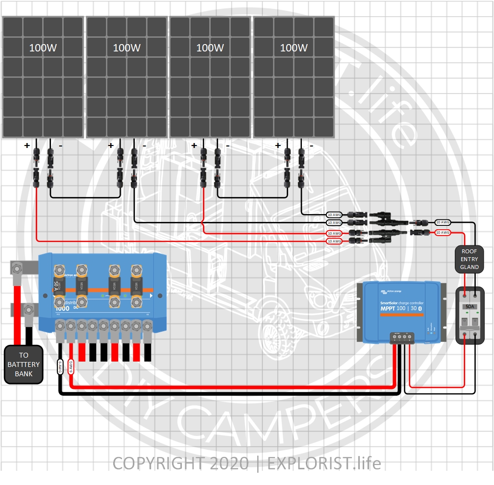
400 Watts – 4x100W Solar Panels (Click to Expand)
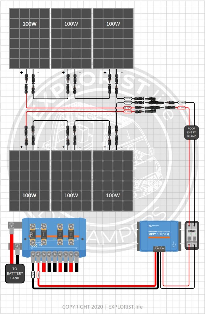
600 Watts – 6x100W Solar Panels (Click to Expand)
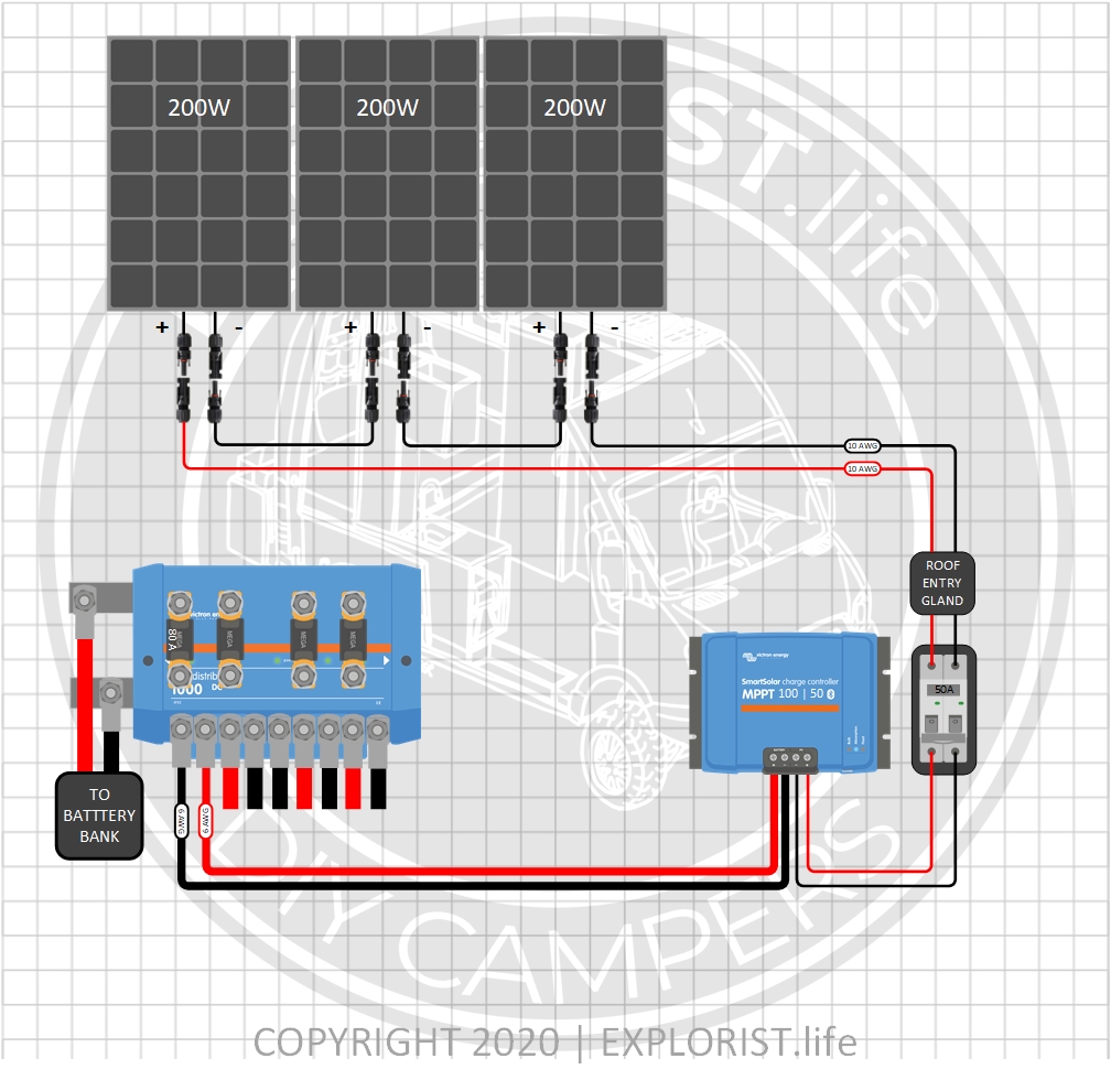
600 Watts – 3x200W Solar Panels (Click to Expand)
Order of Operations for DIY Camper Solar Install
This list is a rough guideline of what order things need to be connected for systems using this wiring diagram. THERE IS MORE TO KNOW about this process, though, in the user manual for each component. READ THE USER MANUAL FOR EACH COMPONENT as this ‘order of operations’ does NOT supersede anything in the user manual.
- Arrange all parts & components where they will be mounted
- Mount & secure all components to the wall/enclosure as necessary (EXCEPT Lynx Distributor)
- Wire battery bank together
- Assemble Lynx Distributor, master disconnect switch & shunt assembly
- Mount Lynx Distributor to wall/enclosure
- Verify Main switch is in the “OFF” position
- Wire Positive wire from Lynx Distributor to Main fuse
- Wire Positive Wire from Main fuse to Battery Bank
- Wire Negative Wire from Shunt to Battery Bank
- Connect negative wires from Lynx Distributor to Inverter/Charger, Charge Controller & 12V Fuse Block
- Install fuses inside of Lynx Distributor
- Connect Positive Wires from Lynx Distributor to Inverter/Charger, Charge Controller & 12V Fuse Block
- Connect Positive Wire from Lynx Distributor to B1 Terminal on Shunt
- Verify dual-pole disconnect switch for solar array is ‘off’
- Connect Charge Controller to Dual Pole Solar Disconnect
- Connect wires going to solar array to dual pole disconnect
- Cover Solar Panels with Cardboard
- Connect solar array together (Order does not particularly matter)
- Remove Cardboard from Solar Panels
- Verify proper solar array voltage at dual pole solar disconnect
- Remove ‘wire bridge’ on Victron Orion DC DC Charger
- Connect positive & negative wire from Orion to Starting Battery pos & neg (as per user manual)
- Adjust Orion Output Voltage Setting as appropriate in Victron Connect app
- Connect 10/3 wire from shore power inlet to Inverter/Charger
- Connect 6/3 wire from Inverter/Charger to AC Breaker Box
- Verify all 120V breakers in breaker box are ‘off’.
- Connect AC Branch Circuits to AC Breaker Box if not already connected
- Connect DC Branch Circuits to 12V Fuse Block if not already connected
- Connect RJ-11 cable & BMV-712 Monitor Gauge to Shunt
- Verify proper voltage between main fuse & shunt (Approximately 12V-14V)
- TRIPLE CHECK THAT ALL WIRES ARE CONNECTED, POS (+) TO POS (+) & NEG (-) TO NEG (-) (except series wired solar panels) AND CONNECTED TO THEIR PROPER PLACES IN THE COMPONENTS AS PER THEIR USER MANUAL
- Turn on Master Disconnect Switch
- Turn on Dual Pole Solar Disconnect
- Replace wire bridge in Orion
- Turn Inverter/Charger ‘On’.
- Turn on Main AC Breaker in Breaker box & Branch Circuit breakers
- Configure system charging through the parameters as per user manual of each component

214 Responses
Another question can I increase my battery bank to 640 Ah without hurting the 2000W inverter/charger and still rely on the 800W solar array? Or would it be better to upgrade to the 3000W inverter/charger?
There is no issues adding additional battery bank capacity.
Hi Nate,
Can I use an 800 watt solar array with the 2000 watt inverter on a 320 Ah battery?
This seems like a perfect wire diagram for my needs, but I feel the need for higher watt solar because I live in the PNW, where the sunshine is limited. Am I on the right track by increasing my solar power?
Russell
Yep! You can swap in any of our solar charging wiring kits (for 12v battery banks) into this diagram without problem: https://shop.explorist.life/product-category/all-products/camper-wiring-kits/solar-charging-wiring-kits/?filter_battery-bank-voltage=12v&query_type_battery-bank-voltage=or
Nate,
Thank you for your content, it is very helpful. I am looking at purchasing an expedition type camper/trailer in the near future and planning for a solar set up like this one. My question is would it be feasible to replace the Battle Born batteries for an EG4 Lithium battery 12.8V (12V) 5.12kWh with 400AH server rack type battery? Seems like this would be a pretty compact set up.
Thank you
Mike
I wouldn’t say so, no. Ch 4.2.1 of the EG4 user manual specifically says to mount to a “structural frame to
prevent vibration”; which sounds like those batteries aren’t meant for ‘vibration prone’ installations like an expedition camper and would likely void the warranty due to “Using product in applications other than which it was intended for by manufacturer”. Battle Born Batteries are specifically designed for mobile applications. Do it once, do it right. 🙂👍
Hi Nate,
I did purchase this wiring diagram for help with wire gauging etc and general layout and to basically help you guys out as your videos have been a great help over the last few months of research.
My issue being I have no copy of the above. I though I had downloaded it but apparently not and I don’t have a copy that was sent to my email.
Any help on this matter? I have a receipt for the purchase the other day if needed. Feel free to email me if you need any details.
You’ll want to submit a support ticket here to get a replacement: https://shop.explorist.life/support/
Thank you Nate!
I so appreciate that you are sharing your knowledge and possibly saving lives. You are a huge help and influence in my solar design and I feel a lot more confident in my choices of Battle Born batteries and Victron control system.
If I may ask a question – I have limited space for solar, so I have 400w to put on the roof (2 x 200w 12v in series) for 300ah battery, and have been toying with the idea to have an intermittent use portable panel with a port in the side wall. I just bought a MPPT 100/50 for room to grow – do I need another charge controller for this intermittent panel or can I wire it in parallel and use one?
You’d want a 2nd charge controller. One for the roof and one for the ground deploy array. How to wire multiple charge controllers in the same system: https://www.youtube.com/watch?v=N0UB7LZVduk
Hi Nate. At 44:57, you show the installation of the solar isolator disconnect (which looks to be 63A from the description on your store), but I don’t see this in the wiring diagram. I do see what looks like a 50A breaker on the wiring diagram between the charge controller and the solar array. Is this the same thing?
This is the most up to date product we are recommending for what you’re talking about: https://shop.explorist.life/shop/all-products/switches-disconnects/solar-isolator-disconnect/
Hello Nate,
I would like to add a second dc fuse block up closer to the front of my van so I don’t have to run as many wires all the to the back. I’m using a Lynx Line In modified for fuses (Thanks for the tip) but do not have another space to add another line for the second fuse block. It would be cost prohibitive to add a second Lynx for one line. Can I continue the line going from the Lynx to the fuse block to the 2nd fuse block? If so I know I would have to use the proper gauge wire for the distance of the run, would I also have to increase the fuse size. I’m still connectivity the same number of 12V devices just spread between 2 fuse blocks. TIA
That’s a good idea and is what we will be doing in our ford Transit build series: https://www.youtube.com/watch?v=iga8VotrDqg&list=PLmvhcyi4n0TVfA4XCYJBkzfUXunSON1zX&index=1 We will be running 6 AWG wire from the Lynx Distributor to fuse block #1, and then continuing on over w/ 6 AWG wire to fuse block #2.
Hello Nate,
I have a 1995 5th wheel that I have put a 100ah battle born lithium battery in. I have upgraded my converter charger before I added the lithium battery. Got the ok from battle born. Now I want to change to a 2000 watt inverter charger. Your diagram states “This system is most suitable for systems that do not have a pre-existing house electrical system installed.”
My rv is already house wired. Not sure how to go foreword. I have 100 watt solar going to add another 100.
Any help would be thankful.
Thanks Rod
I have examples of how to set these systems up on both 30A and 50A shore power here: https://www.explorist.life/solarwiringdiagrams but both of those are, at this time, for 3000w+ inverter chargers; but should give you the right idea.
Nate,
I did an energy audit with your spreadsheet. A 2000 watt inverter would work for me. However, it is cheaper to get the battle born energy bundle with 400 amps of lithium batteries with a 3000 watt inverter. What are the downsides for having a larger then needed inverter. How much more power will the 3000 take to run than the 2000?
Kevin
Hi Nate,
First of all, thank you so much for making this tutorial!
I was wondering if there is anything wrong with using 2 200w solar panels in this setup. I don’t think I have room for 3.
Thanks!
There are all kinds of solar array setups compatible with this system: https://shop.explorist.life/product-category/all-products/camper-wiring-kits/solar-charging-wiring-kits/
Hey Nate,
I have a high output alternator and no solar. The diagram above matches my setup the most, however I have a 100amp Victron Buck-Boost instead of the 30amp DC to DC Charger.
How do I adjust the diagram to include 100 amps from the alternator and not having solar? I suspect my wire gauge, distribution panel, circuit breakers, and likely other parts need to be slightly different.
And, would you recommend installing a BatteryProtect by Victron?
Thank you!
Sure! So… Simply omit everything on the solar charging leg all the way from the Lynx Distributor to the Solar Panels if you don’t want solar charging.
For the Buck Boost… You’ll want to substitute the 6 AWG Wire and 60A fuses on each end for 2 AWG wire and 150A fuses on each end. The Buck Boost doesn’t need a negative wire going from the Buck Boost to the starting battery, so that can be omitted and the only negative would go from the Buck Boost to the Lynx Distributor.
You don’t need a battery protect when using Battle Born batteries.
Cool setup!
Your posts are very informative and I refer everyone that has an electrical question to your site. I was wondering what software you use to draw your system diagrams? I’d like to document my system for my own reference.
Thank you!
I use Microsoft Visio to make all of my diagrams.
Hi Nate
When connecting the solar charge/controller you call for a 50amp fuse but on the diagram it shows a 70amp fuse. which is correct? we have 200ah batteries and 400w solar.
i have the 100v/30amp mppt. my batteries are battle born.
Thanks
50A (or 60A… whichever is available) for the 100|30. This should help: https://shop.explorist.life/shop/all-products/camper-wiring-kits/solar-charging-wiring-kits/400w-solar-charging-wiring-kit-4x-100w-12v-battery-bank/
70A or 80A fuse would be for the MPPT 100|50 as shown on the diagram.
Thank you so much for this valuable information! I am purchasing my supplies using this list. I have noticed there is some overlap, with some items (for example, the inverter) listed more than once. As I try to determine how many lugs I will need or how much shrink wrap I may need, I am finding it hard to wade through this list in a way that does not result in my purchasing much more than I may need. How can I determine where the overlaps are?
The ‘shopping list’ is the consolidated version of the ‘parts list detail’ section and should have minimal overlap.
Nate, thanks for all you clear video’s and diagrams. I have a question on your solar array 400W. I have 4x110W Sunpower panels 2s/2p with a Victron 100/50 charges (potential expansion in the future for total 660W array). What size breaker do I need in the Victron Lynch 50, 60 or 80 Amp? Thanks
80A fuse w/ 6 AWG wire from the Lynx Distributor to the MPPT. Given the Open Circuit Voltage of your panels is in the 18V-25v range, you could swap your panels into this plan: https://shop.explorist.life/shop/all-products/camper-wiring-kits/solar-charging-wiring-kits/600w-solar-charging-wiring-kit-6x-100w-12v-battery-bank/ but wire the panels like this for the time being: https://shop.explorist.life/shop/all-products/camper-wiring-kits/solar-charging-wiring-kits/400w-solar-charging-wiring-kit-4x-100w-12v-battery-bank/
exactly what mega fuses do i need with 400 watts solar and 200 amp hour batteries on the lynx distributor? the picture says 70a, 50a, 100a, and 300a, but i do not see all of these fuses on the products list.
Should be fixed now. 300A for Multiplus. 100A for DC Fuse Block. 60A for the Orion. 60A for the MPPT 100/50.
Nate,
I have purchased the Orion DC-DC Isolated charger and am getting ready to wire it up per your 200-400AH wiring diagram for my 2020 Sprinter 2500 (170WB). I am seeing recommendations to wire this device into a positive bus bar which resides in the battery compartment next to the engine battery under driver seat. Do you have experience wiring into this bus bar? And would you still recommend wiring the negative cable directly to the battery or would chassis ground suffice?
Yes! Check out how I made that connection in this video: https://www.youtube.com/watch?v=01F4QDVJUq0
Hey, Nate; I’ve got a question. I’ve got a 400 A ANL fuse for the battery bank along with a 400 A fuse in the distributor going to the inverter. Since these are going to be installed close together and inside a “shell” for my setup, do I really need the 400 A ANL fuse on the battery? I’ve got maybe 2-3 feet of wire between the battery and the distributor.
Thank you, sir!
Indeed you do! For a few reasons:
1: ABYC E-9.10(a) states that “Ungrounded conductors other than cranking motor conductors SHALL be provided with overcurrent protection within a distance of 7′ of the point of which the conductor is connected to the source of power measured along the conductor.” (There are some exceptions for the distance the fuse can be; but no exceptions for omitting the fuse).
2: Omitting the main fuse would leave the wire from the battery bank to the Lynx Distributor AND the Lynx Distributor unprotected from short circuit AND overcurrent during high energy usage even during the event that the Inverter/DC Fuse Block/Charge Controller/etc circuits are individually operating within spec.
3: This main fuse must be either an ANL, Class-T, or MRBF Fuse as a MEGA fuse does not have a high enough AIC (Amp interrupt capacity) to break connection to a lithium battery bank (ABYC E-11 table IV)
What is the best option if you do not want to purchase the Victron distributer? I’m a bit lost on sizing the bus bar and where to get those components?
Yeah, I don’t know. I guess you’ll just have to piece it together based on what you think is best. IMO there isn’t a reason to NOT use the Lynx Distributor (or a modified Lynx Power-In): https://www.youtube.com/watch?v=548aRhZMN-g
Are ferrules not required or recommended for the 2/0 wires?
Also, the WFCO panels are out of stock everywhere, any recommendations for an alternative? (The Furrion ones are sub-par construction)
All 2/0 wire in this diagram uses a wire lug; not a ferrule, so it’s not necessary.
Stephanie is working on securing a better source for those panels. It’s proving challenging. Will update soon.
@Nate Yarbrough, Were you able to find a good quality alternate for the WFCO panels? They are still hard to come by.
Yep! We just released them in our store: https://shop.explorist.life/product-category/all-products/distribution-panels/
Hi Nate, thanks a mil for all this great content. Studying my recently purchased diagram and the respective shopping list, I can’t seem to find a reference or link to a specific shunt to connect BMV-712. Would you be so kind to specify what you use ? Thanks in advance, Ferry
There is a shunt included with the BMV-712.
Will any parts change on the 2000 watt inverter list if I want 50 amp shore power instead of 30 amp?
Yes. Pretty much the entire diagram would need to change. Here is a 50A RV Retrofit guide that will point you in the right direction: https://www.explorist.life/50a-camper-inverter-with-solar-alternator-charging-wiring-diagram/
Hi Nate,
love your videos and information – sets things out really well! I’m over in the UK and the shore power runs at 240VAC, so can’t use the WFCO AC-DC Distribution Panel, as it runs on 120VAC. I’m presuming that this could be replaced with a separate AC distribution panel and a DC fuse panel, such as one of the Blue Sea fuse boxes? Or is the WFCO AC-DC actually converting the AC to DC? Looking at Victrons various system schematics, I think the multiplus will power both the AC and DC loads when on shore power, as well as charging the battery?
Thanks,
James.
The WFCO panel is simply an AC breaker box and a 12V fuse block. It is doing nothing more than fusing and distributing power.
5/27/21
Hi Nate,
I purchased the 2000W INVERTER | 200-400AH LITHIUM | 200 TO 700W SOLAR CAMPER WIRING DIAGRAM and was a member of the private group for 4 months -Dec 2020-March 2021-unfortunately at that time I was unable to proceed with wiring my electric because of covid & winter, and discontinued my membership because I could not make use of it.
I’m now back to doing the electrical wiring again and wondering if you can answer 2 questions-
1. I have the Victron Lynx Distributor-that was recommended to purchase for this electrical diagram.
In the diagram, above, it shows 9 lines coming out from the bottom,
But the actual Lynx Distributor only seems to have room for 6 lines coming of of the bottom–is there a way to double up or add in lines to make up the 3 lines missing? I can send pictures if needed.
2. Into where do I wire in for the 12 volt electric wiring? (I have three 12 volt fans and 9 puck lights)
Thanks.
All best,
Joy
1: There are 9 studs in the lynx distributor. 4 positive, 4 negative and 1 on the negative busbar I use for the equipment grounds.
2: Branch circuits like lights and fans would be wired to the 12V fuse block in the AC DC distribution panel (on the DC side).
Can I get a printed list of parts and instructions?
Sure! You can right click anywhere on this page and print the page.
Hey Nate thank you for all this! I accidentally bought the non isolated charger and was wondering if I can still use it for this setup if so how? Thank you!
Yes. Just omit the negative wire to the starter battery from the orion.
To clarify, the two items I am asking about is the Li-BIM and the Orion Charger
This diagram uses the Orion to charge from the alternator and not the Li-BIM.
@Nate Yarbrough, Thanks, so since I have the Li-BIM already, should I use the old parts list or is that the only difference?
Personally, I would recommend returning the Li-BIM and buying the Orion so you can use my most up-to-date diagram Here is why I swapped out the Li-BIM for the Orion in my diagrams: https://www.explorist.life/how-to-charge-diy-camper-van-batteries-with-vehicle-alternator/
Nate,
I purchased my batteries, inverter/charger, solar controller and Li-BIM Lithium Battery Isolation Manager from battle born. I was then going through the parts list from your updated wiring diagram and it shows an Orion – Tr Smart 12/12v – 30 a Isolated Charger.
Do these two items do the same thing? Have I messed up by mixing the two lists?
Tim
This diagram uses the Orion to charge from the alternator and not the Li-BIM.
Hey Nate,
I purchased your wiring diagram for the 2000W system and the pair of Lynx adapters from your online store. Today I received the Victron 100/30 charge controller and Lynx Distributor. I’ve connected the charge controller to the Lynx and it seems to be working fine. My question is about the number of connections in your diagram to the Lynx. Your wiring diagram shows a total of 9 connections but the Lynx I received only has 5 connections on the negative (lower bar) plus 1 other one on the right side. Could you please clarify for me how I will add the inverter/Charger, Orion dc/dc Charger, 2/0 ground, and (2) 6 awg wires to the WFCO panel?
Thanks,
Don
There are 4 positive connections and 5 negative connections in this diagram. There are 4 positive connections and 5 negative connections in the Victron Lynx distributor. Maybe watching this video will help with understanding how this all works together: https://www.youtube.com/watch?v=JMqtVBN26NQ
Most shore power schematics I’ve seen put a 30A main circuit breaker between the shore power plugin and the inverter. Why don’t you include one?
Same reason there isn’t a breaker between the wall outlet and your toaster. There is a breaker in the breaker box or shore power pedestal that is protecting that circuit.
Hello! Do you have a recommendation if our van battery will be more than 5 ft away from the bench where my electrical system will be? Is the 6 AWG wire still sufficient? Can this wire be tucked into the wall?
Yep! 6 AWG will still be good to go for the Orion and yes, it can be tucked into the wall.
Hey Nate,
I was thinking of going with a very similar setup but I don’t see the need for an inverter / shore power with what I have planned. Is it possible to forego that for now, with the option to expand in the future?
With the proper application of planning and design… anything is possible. 🙂
One other question…
Do I need to order both the Orion-TR Smart 12/12V-30A Isolated Charger and SmartSolar MPPT 100/30 Charge Controller with Bluetooth if I am planning 400 Watts of solar? Or only one of those? It’s not completely clear and I don’t want to order something I don’t need. Thanks in advance!
The SmartSolar MPPT is for charging via solar.
The Orion is for charging from the alternator.
Hey Nate! Thanks for sharing all of this helpful information. I was getting ready to order everything and noticed the item “Uxcell IP65 ABS Transparent Cover Power Distribution Protection Box for Circuit Breaker Indoor on The Wall 5 Way 120mmx160mmx92mm” is out of stock. Is there something else you could recommend instead? Thanks!
Looks like it just came available again with an in-stock date coming up soon.
The information or your sight is fantastic, and starting to make sense.
Thanks!
Short version: How many batteries minimum for 3000w inverter?
I am building on a 144 sprinter with the end goal of:
x4 100ahr batteries
x4 100w solar panels
DC-DC charger.
30 Amp shore.
So I got the 2000w-Inverter-400Ah-Lithium-700W-Solar pdf diagram as the closest.
Initial build out is to be with just x2 100ahr batteries.
I think I saw you reply that to a post that 2 batteries was the minimum for feeding a 2000watt inverter.
Any downside to using the 3000 watt inverter/charger instead of the 2000watt?
I understand I would have to up the wire size and fuses.
Reason would be if we add a bosch water heater.
Would x2 100Arh batteries be enough to feed it?
The information or your sight is fantastic, and starting to make sense.
Thanks!
reference: “Bobby Jackson” question dated September 7, 2020 at 07:30 AM
The Multiplus 3k needs 400Ah of battery bank capacity as per pg.8 of the user manual.
Hello!
(1. Is the number of 100AH batteries the only difference between the 200AH and 400AH systems? 2 vs 4 batteries.
(2. I understand that “As a general rule, you want to have twice as many watts of solar as you do amp hours of batteries.” So would 600 watt solar system be too excessive for a 200AH system?
thanks!
1 Basically yes. Some extra lugs, wire, heat shrink as well.
2: That would be fine. It would just charge faster.
Just curious on your thoughts about grounding. I have a system similar to the 2000w inverter and 300amp hour batteries. No dc to dc charger so system is totally separate that main battery. I see some people saying the house batteries shouldn’t share the common chassis ground or there is no advantage since the system is separate. Also grounding the house and car both to chassis might create issues.
Any GFCI outlets need a chassis ground to properly function. I recommend using a chassis ground for the house system as per this diagram.
Hi Nate!
Found your site and it has been a life saver in designing my system. So much so I bought a couple of your diagrams and info packets. I did have a question regarding the fusing for my specific solar and dc/dc charger setup. I’m going to have 480 watts of Renogy solar in 3 panels (series) on the van. I’m planning on using the 100/50 victron controller and believe a 50 amp megafuse in the lynx would be appropriate for this? Also, I’m going to have the victron 30 amp isolated DC charger and was a little unclear on the fuse size in the lynx. Would a 50 amp megafuse work for this as well?
Cheers!
Nick in VT
For your setup, follow the “600 Watts – 3x200W Solar Panels (Click to Expand)” solar diagram at the bottom of this blog post for the solar array portion of your setup.
50A fuse for the 30A DC DC charger using 6 AWG wire as per the diagram is indeed sufficient. (60A fuse is also fine if you are having a hard time finding a 50A fuse).
Hi!
Instead of a mega fuse installed directly on the starter battery, you recommend a terminal fuse, which looks like it would stick up too high (on a Promaster) starter battery area. By chance can you show a close-up picture of how to connect this terminal fuse?
Thanks!
The terminal fuse is a ‘blanket statement’ of what SHOULD work for MOST scenarios. If the terminal fuse is too tall for your particular application and you feel that a MEGA fuse would work better, go with that.
Hey Nate, thanks for instilling the confidence to do my own electrical system! I’ve spent a lot of time on your site, watching your videos and yes, I did purchase a couple wiring diagrams! I initially made your busbar and recently upgraded to the lynx distributor. With the previous system, regardless of the master switch being on or off the solar panels would charge the system. With the new setup, this isn’t the case correct? Also, if the master switch isn’t on while driving the battery bank won’t be charged from the dc-dc charger BUT the electrical system will essentially be live due to the power from the alternator? Thanks again for all the help.
Yes, that’s correct on both accounts.
Great website. Where do you get the symbols for all your diagrams?
Thanks! MOST of the Victron ones are from Victron. The rest I’ve made myself.
Hey! I noticed that the fuses listed in the parts list for the Lynx Distributor are different than those shown in the wiring diagram. Do you mind clearing that up? I’m doing a 2000w, 200ah build and I purchased a 300 amp, 60 amp, and 100 amp MEGA fuse.
If they are within 10A of each other (50A vs 60A), either will work just fine. Sometimes there is a discrepancy as one size will go out of stock and I replace it with the closest applicable size.
Thanks! So, If I’m using 4x 160W Newpowa panels, can I use the 4×100 plans?
Use the plans: “600 Watts – 6x100W Solar Panels” and just omit one panel per series-string.
Hey Nate,
Why the two 3/8″ lugs for the 2/0 cable in the Battery-Busbars section while the rest of the lugs are 5/16″? Are those for the Lynx?
Thanks for the article!
They attach to the main disconnect and the shunt.
Hi Nate, I’m studying your drawings intently and adding to my cart using your links. Your drawing for the 2000W Inverter/Charger with 400 watts solar shows a 50A Mega fuse for the B2B but your link calls out a 60A Mega. So am I good with the 60 or go for the 50? Does it matter?
Secondly, I am assuming based on the same drawing I also need a 70A Mega fuse for the shunt/battery monitor although there is no link to one in your list. Am just double checking before I pull the trigger. Your drawings are great as well as your videos. Very helpful. Thanks. I’m on my way.
50A vs 60A doesn’t matter in this case. Just whatever is in stock is fine.
The fuse protecting the wire from the positive busbar to the Shunt is included with the Victron BMV-712 Battery Monitor kit.
@Nate Yarbrough, Cool. Thanks for the prompt response. I’m all in on your 400 watt set up. Parts on the way. Many thx.
Great! glad it helped.
@Nate Yarbrough, what about the 70 Amp MEGA fuse shown for the Solar Charge Controller? If I have a choice between 60A and 80A available from Littlefuse, which one should I use?
Either is fine. I’d opt for 80A for a bit of headroom against nuisance trips; but either would be fine.
Hi Nate!!!! Finally have the cash and building out my solar set up. The only thing that I didn’t order yet is the Lynx distributor. I did a quick Internet search and I see there are two similar parts:
– Victron Energy Lynx Distributor DC Distribution system (you recommend) ~$206
– Victron Energy Lynx Power In ~$137
It LOOKS like the only difference is LEDs to tell you if a fuse is burned out.
Is this a feature that you have found a real need for? Is it not obvious that a fuse is blown when you pull the panel. (In my mind I am thinking back to the old screw in round fuses and it was obvious when they were blown.)
THANKS IN ADVANCE!!!!!
Kirk
The Lynx Distributor has fuse holders. The Power In does not and is therefore not what is needed.
@Nate Yarbrough, That was VERY silly of me! I just looked at the photo again and see that there is only one row of of nuts! Thanks so much for helping my lack of immersive vision! 😉
If I am using a Sterling 1260 as opposed to the Orion, how will that affect my wiring diagram? I’m following the same grounding technique that you show above, so does that mean I just need a positive wire going from the Sterling to the car battery, a negative and a positive from the lynx to the Sterling, and that’s it since the Lynx is being grounded where the shunt and lynx connect? Or is some other grounding method required?
Dear Nate, hope your safe this days.
Im following you since the day I decided to buy a caravan ( not campervan)
Thank you for all the information your giving to the community .
Most of the electric is the same so no diffrend beide the starter battery ( but its not relevant to my question)
Im trying to understand, you never mention this in your videos I think and from your diagram
And actually even I emailed Victron and didn’t got clear answer
So my setup is very simple
4 x 100 watt pannel – connected to combiner box (cables follow your recommendation)
1x 100 amp gel battery connected in series
2 main bus bars (positive and negative )
1 victron mppt 100/30 connected directly with fuse to battery
1 2000 watt TBS inverter with smart shunt and 250 amp mega fuse
All my connection today(beside the victon charger ) goes to the main busbars
So my question finally 😂 is :
Now – I’m installing new 2 x100 amp lithium battery
What is the rule regarding the solar charger – should the + and – from the vicrton solar charger needs to go to the bus bar or to the battery
Thanks
And I wish you had more content for cravans also ..
The positive and negative wires coming from the charge controller CAN go to either the batteries or the busbar. I recommend wiring it to the busbar for the sake of easy wire management. Wherever you wire them… Make sure that ALL loads and chargers (including the negative coming from your charge controller go to the ‘Load’ side of your SmartShunt.
For the wiring coming from inverter to AC panel. Is 10-3 acceptable or 6-3 really the only option there? The distance from the two is about 18” max.
10/3 would ‘work’ but you would be handicapping the PowerAssist function of that expensive Victron Multiplus you’ve bought. May as well do it right and just do it once.
Hi Nate! I’ve asked you a few questions before on your youtube channel and on here. I originally made your copper bus bar and have everything set up, but when I saw your new diagram, I decided to not risk it, and just go with the Lynx. Someone else mentioned it, but I guess I just wanted to make sure it was safe. It looks like on this version of the build, the charge controller will be shut off if the switch is shut off, as opposed to the old system where the charge controller was still allowed to charge the batteries. Now I assumed this wasn’t safe, because then you’d have a connection between the solar panels and CC, but no connection with the CC and batteries. So if I ever have to turn off my system, does that mean I need to hit the breaker for the panels first? Just so the CC doesn’t get fried?
You should indeed turn off the solar breaker first, but if you don’t, it’s not a big deal (at least with Victron charge controllers, I can’t speak for all brands). The charge controller will simply cycle on and off until it senses a battery voltage. It won’t damage the charge controller though; it’s just good practice to turn off the solar array when disconnecting the charge controller from the battery bank.
Hello, just purchased this wiring panel! Excited to get started. Looking at breakers now though. Not quite sure on the breaker size from the inverter. I’m using a 1500 watt pure sine inverter and x2 125 ah AGM batteries. I was think a 20 amp breaker but then read about occasional surges and wasn’t sure if that meant I needed to size up or not. Any help would be appreciated. Thank you
The ‘Main’ Breaker in the breaker box coming from the Inverter is a 50A breaker when paired with the 6/3 wire paired with the 2000 Multiplus.
Hi Nate,
Based on the power audit I did, I need 100Ah battery and 200 W solar panels, 1000 W inverter. I was wondering which one of these diagrams best apply to me? \
Thanks
I don’t have any diagrams that are that small, but the diagram that is on THIS page would definitely cover those needs. For needs that small though… I generally recommend an all-in-one unit like a Goal Zero.
Good day. Is it possible to have a similar setup with a 2000 watt inventer / charger on my boat? Of course with marine grade wire. best regards Jeen from the Netherlands.
You can indeed use the prinicples found here for marine applications. Just be sure to follow whatever rules/standards that are required for your area.
Hi Nate. I recently bought you wiring diagram for the 200-400 AH lithium, 200-700 watt solar setup. This has been invaluable, so thanks for creating this! For the connection to the Alternator from the Victron Isoloated DCtoDC charger: I own a new 2020 Sprinter 144 Cargo van, and the terminal fuse you recommend for the positive connection does not fit on the starter battery terminal under the drivers side floor. MB discourages connecting anything to this starter battery. Since my van did not come with the option of an auxiliary relay(under the driver’s seat, where I would have been able to connect directly), I am planning on running a short 6AWG cable from the starter battery to the area under the seat (against MB’s recommendation..) and then connecting that to a 60 amp surface mount breaker, such as this one: https://www.amazon.com/gp/product/B07PBGMMNZ/ref=ox_sc_act_title_2?smid=ALHXFZX1L0DAX&psc=1, and then connecting that with 6AWG cable to the Victron charger. Have you done this yet with the newer 2019/2020 sprinters and would you recommend this approach? Thanks Nate! -Russ
Yes, I like your proposed solution and is what I would recommend.
Hi Nate,
Really enjoy your videos and blog. They are helping me out a lot as I plan my system. If my panel has just a 30 amp main, can I use 10/3 wire from the Multiplus 2000 if it is set to 30 amps? Sorry if this is a duplicate question.
Thanks!
Mike
Correct. That’s what I recommend on 30A OEM RV Retrofits here: https://www.explorist.life/30a-camper-inverter-with-solar-and-alternator-charging-wiring-diagram/
Hi Nate, we are upgrading an existing 12v DC only system to replicate your diagram above. In your diagram, your 12v DC and AC fuses are in a distribution panel together. Does it make sense to keep our existing 12v DC fuse panel and add a stand alone AC panel to reduce costs and use what we have? If so, how would you recommend altering the diagram to split the power between the two separate DC and AC panels? If it makes more sense to stick with your diagram and use the dual distribution panel, that’s fine too. Just wondering. Thanks!
In that box… the AC side and DC side are totally seperate, so if you want to use seperate boxes the wiring is the same… just to two seperate boxes.
I don’t have an inverter/charger in my system and currently have my master ground coming from the center stud of my Lynx distributor. Do I need the 2/0 ground you have shown connected between the Lynx and the BMS shunt?
With no Inverter and dedicated positive and negative wires going to all loads… there is no need for a chassis ground.
Hi Nate, thanks a ton for all the info and resources you have supplied! I’m looking to DIY install the above system in my 2020 144. Is there an add all shopping list? I noticed the list above doesn’t include the mppt, is there anything else that is left out? And lastly I’m having trouble locating the interactive diagram with rollover details.
There is no longer an ‘add all to cart’ function. That function caused more problems then it was worth. With that, it was nearly impossible for me to keep up with providing links to products that were actually in stock. The “Parts List” on this page, though, is the consolidated version of the parts required to make this setup. I’ve updated the video on this page to reflect the current setup and changes.
Hi Nate! I have a Victron Multiplus 3000 watt invertor but only want to have 2 x 175w panels and 2 battle born 100 Ah 12V LiFePO4 Deep Cycle Batteries. Will the inverter be too big for this setup?
Yes. A 3000W Inverter needs, ideally, 400Ah of batteries. 300Ah as a BARE minimum.
Nate,
Thanks for all the info. One question on wiring. I plan on using the lynx distribution panel but I’m using a separate charger and inverter So I will have 5 objects to fuse and connect to the battery. Any recommendations on how to wire everything together if you needed to add a charger and inverter separately in this diagram?
Regards
Jeremy
The best and easiest way would be to use an Addional Lynx Distributor. Those Lynx Distributors are designed to be bolted together, end to end, for more spaces as necessary.
Thanks for the work you do. I’m planning to use this 2000w Inverter, 400Ah-Lithium, 700W-Solar wiring diagram to install 200-300Ah system with 200W of solar.
For budgeting and build-time purposes I plan to start with 200Ah, alternator charging, and 12V distribution. So per your diagram I’ll buy two BB batteries, Orion DC-DC charger, Lynch distributor, a DC fusebox, and all necessary wiring.
With this in mind, any advise on doing this part first and then adding the solar and inverter etc later?
I recommend starting with the ‘end goal’ and working backwards from there. Adding the Inverter/Charger and the solar charging leg later should not be a big problem, but just be aware that you won’t have the ability to charge via shore power.
Hi Nate.
can this diagram (2000w INVERTER | 200-400Ah Lithium | 200 TO 700W SOLAR Camper Wiring Diagram) connect to two 200 watt solar panel? also can this use 3000w inverter instead of 2000w inverter? and last question ,run the cable underneath the van to the Alternator better or under the subfloor inside the van better?
thank you.
This diagram is not compatible with a 3000w inverter, but this one is: https://www.explorist.life/3000w-inverter-400-600ah-400-to-1200w-solar-camper-solar-kit/
I would try to run the wire from the starting battery along the wall as opposed to under the floor.
the diagram has been very helpful so far. just curious where the positive from the batteries is supposed to be connected as it looks to stop short of the battery switch. also what style of battery swicth do you recommend?
The wire gets connected to the battery switch even though in the illustration it stops short. I have a switch recommendation in the parts list on this page.
Hello Nate. I just purchased your wiring diagram for the 200 to 400 AH, 200 to 700 Watts solar setup. I have a question on the DC-to-DC charger since your link is broken and BattleBorn has two units; one is isolated and one is non-isolated. Your wiring diagram shows the isolated version but it is not clear that is what you intended. Can you tell me the difference and what you would recommend? Thank for the valuable information! -Russ
The link is fixed now, but I recommend the Isolated version (and is what this diagram shows).
Hey Nate, my question is regarding the 60A terminal fuse. The link on this page only has 30a, 50a, 80a, etc as options, but no 60a. If I’m using a Orion 12|12|30, would I be safe in choosing a 30a or 50a fuse? Thanks!
Quick question: If I were to use my House Battery @ 24V, instead of 12V, could/should I use a smaller gauge cable (eg: 1/0 instead of 2/0?
You could, yes. Smaller fuses would also be required. Ultimately, though… this diagram is not really compatible with a 24V battery bank. A lot would need to change. Here is an example of a system with a 24V battery bank: https://www.explorist.life/24v-6000w-120v-240v-split-phase-camper-solar-wiring-diagram/
Would this setup work with 800W of solar panels? Thanks
Not directly. You would need a larger charge controller and bigger wires from the charge controller to the Lynx Distributor. See this diagram for an example: https://www.explorist.life/3000w-inverter-400-600ah-400-to-1200w-solar-camper-solar-kit
Why do you use such a large fuse/breaker in between the solar panels and the charge controller? On another page, you explain how you may not even need one, and describe how a higher amperage fuse is practically useless because of the narrow window of lower amperages coming in from the panels.
I have 6 100 watt panels. I already have my system set up with 4 100 watt panels but Im adding two more. I just upgraded my controller from a 30amp to the victron 100/50 amp. I was planning on wiring them in 3 series of 2 and the 3 strings in parallel but I want to avoid adding fuse boxes to the roof. Would it be better to wire them in 2 series of 3 each to avoid individual fuses on the series and just one 60 amp fuse before the controller?
If you are wanting to avoid fuses on the roof, you would need to wire the array: 2 sets of 3 panels in series with the 2 series strings wired in parallel. There is an example of this under the “600 Watts – 6x100W Solar Panels (Click to Expand)” dropdown at the bottom of this blog post. If you went with 3 sets of 2 panels wired in series with the 3 series strings wired in parallel, you would need to install MC4 fuses as shown in this video: https://www.youtube.com/watch?v=b2H8vpj8rQg
Hi Nate, I’m wiring two 300w panels in parallel, but otherwise following this diagram to a T. Based on the solar charge controller calculator, with the max voltage of my solar array around 45.7V and max amps per panel at 26A (if it reaches -30F), would it be advantageous to use 8awg from the solar panels to the solar charge controller instead of 10awg to prevent any further voltage drop?
Which panels, specifically, are you using?
Renogy 300w
As long as the distance from MC4 combiner to the charge controller is under 20ft, 10 AWG is sufficient.
Hi Nate,
Amazing content, thanks for putting the work in! Had a question I have a 2×100 ah lithium bank and will have a 2000w inverter very close to the bus bar. When I using my wire sizing calculator I do 2000w/12v to get about 167ah. 167 ah at about a 2 feet of combined cable length gives me 6 gauge or larger. Can I get away with that or am I missing something to get to 2/0? Thanks so much!
Victron specifically recommends 2/0 wire to supply 12v DC power to their 2000w Multiplus as shown in this diagram. That’s why that wire size is used. Your calculated 6 AWG would absolutely not work as 167A is more than the max ampacity of 6 AWG wire.
I want to put the 2000w Inverter and the 200-400Ah battery set up in my van, but would just like to buy one 100Ah battery to get started to save some budget for other things. If I follow this diagram can I simply add a second and third battery later?
A single 100Ah battery will not supply enough power to run a 2000w Inverter. I recommend starting with at least 2 x 100Ah batteries and then adding the 3rd one if needed.
I really appreciate all that you have done here. Now I’m ready to do it.
So, I’ve found the appropriate wiring diagram, https://www.explorist.life/2000w-inverter-200-400ah-lithium-200-to-700w-solar-camper-wiring-diagram/, but it certainly is NOT interactive. No matter where I hover or where I click, the diagram does nothing. What am I doing wrong?
You’re not doing anything wrong. That particular diagram is not interactive. I have had MASSIVE problems with my interactive diagrams in the past and have yet to find an actual good solution.
Hi Nate, would it be overkill to add a breaker or disconnect between the MPPT and Lynx to isolate the MPPT if needed?
Thanks
Richard
If I thought it were a good idea; I would include it in the diagram. 🙂 I cannot think of any scenario where the MPPT would need to be isolated that could not be taken care of by using the master disconnect or by turning off the MPPT via the App.
Nate, thanks so much for the diagram and explanations. This was definitely the single best resource for wrapping my head around this stuff. I think I’m almost ready to wire my system just like this one.
Could you explain how you decided on the 300 Amp MEGA Fuse for “Busbar to Inverter/Charger”? That’s in the Lynx distributor right? That seems like too big of fuse for that 2000 watt inverter.
Sure! That size of fuse is recommended by Victron in the Multiplus 2000w user manual. 🙂
Hi Nate, thanks so much for pulling together such great resources for the van-life community! As a novice, I’d be lost without them. I am planning on building an electrical system w/ 300AH Lithium BB batteries and a 3000W Victron inverter and 600W of solar. Would you suggest using this wiring diagram for such a set-up (which fits within the 400AH range but I will have the larger 3000W vs. 2000W inverter) or the wiring diagram for a 3000W inverter | 400-600AH | 400 to 1200W solar kit (which has the correct inverter size, but slightly larger AH battery system)? And whichever kit you suggest, is there any modifications that I will have to make given the slight variation in system size? Thanks so much in advance! And I will be sure to use your affiliate links when purchasing the system.
The Diagram with the 3000W Inverter would DEFINITELY be the way to go as it has all of the 4/0 wire spec’d out to run the 3000w Inverter/Charger: https://www.explorist.life/3000w-inverter-400-600ah-400-to-1200w-solar-camper-solar-kit
Hi there Nate – With a system like this, is it worth it to connect a travel trailer (towable) to the vehicle alternator via a 7-pin connector? Do you have a diagram that shows that kind of setup? If I decide to eliminate an alternator connection from this diagram, what equipment changes and do you already have a diagram like that? Thanks so much – love the work you’ve done here.
Sure! That’s a fine idea. You could simply delete all wires/fuses/components from the alternator to the Lynx distributor in this diagram for that to work.
Nate, we just recently bought an Airstream 26U and I want to install 400W solar. I found your website and YouTube channel, thank you so much for the great description and detailed diagrams/schematics!
Further to Mark’s question and your above response, I have a 2016 Touareg TDI and I’m trying to figure out….
1) Do I need the Victron Energy Orion-TR 12/12-30A to eliminate the issue where when the TV/AS are still connected (via the umbilical) but the TV ignition is off, the AS batteries resting voltage would apparently drop to same resting voltage as the TV battery ?
2) Also, does the Orion take care of the risk to your TV battery if left connected while the TT is on shore power and your lithium converter is putting out a steady 14.4-14.6VDC, which I believe would be bad in the long term for the TV lead acid battery?
3) If I still need the Orion to address above issues, do I just leave your diagram as is but connect the 2 x 6 gauge wires (that you show going to the alternator) to the AS 7-pin plug/connector?
Thank you kindly!
Richard
1: The Orion will isolate your AS batteries from your TV batteries, yes.
2: There is no ‘reverse charging’, so this is a non issue with the Orion.
3: Kindof… but you’ll want to find out what the wire size supplying power to the 7 pin connector is and make sure that there is not too much power flowing through it because of the higher amperage requirement from the Orion and you may have to opt for the smaller Orion 12/12 – 15 unit. For this reason… I generally don’t recommmend charging the trailer batteries from the alternator. Money is better spent on a few hundred extra watts of solar, IMO.
Hi, can you shed some light on your choice of fuse sizes? specifically the solar to mppt fuse?
Between the solar array and the MPPT is simply a dual pole, DC rated breaker which is acting ONLY as a disconnect and does not offer any kind of overcurrent protection. Overcurrent protection in this location is not required. More info: https://www.explorist.life/how-to-fuse-a-solar-panel-array-and-why-you-may-not-need-to/
The dual pole disconnect just needs to be big enough to handle the array amperage, which is why I have a 40-50A breaker in that location. This disconnect is required by NEC 690.17 (B)
Thank for all of your help with the diagrams. In the diagram you have a 6awg wire attaced to the lower left corner of the charge controller. That wire attaches to the lower right hand corner of the inverter/charger. Next to that wire is a 2/0 wire (also attached to the lower right corner of the inverter/charger) that goes to the lynx busbar. Are these wires ground wires? I am probably over thinking, nut could you please explain.
thanks,
Tim
Yep! Those are equipment ground wires. They connect the metal chassis of the equipment to the negative busbar so that in the event of a catastrophic equipment failure, the current has a path back to the battery to complete the circuit so the fuse can blow.
Hi Nate,
I’m planing on installing your 400AH setup exactly like your very well put together diagram, which I purchased. Should I buy the semi complete package you have on battle born web site and get the rest off of Amazon? OR? I thought you had a way to add the whole list to my cart on Amazon?
Hey Leif! You should use the “CAMPER SOLAR PARTS SHOPPING LIST” in addition to whatever solar parts you need from the dropdowns at the bottom of this blog post as your shopping list guide. Not everything is from Amazon, so there is not an ‘add all to cart’ function.
Hi Nate,
I’m going with this setup using a single 200ah Victron battery.
Do you still recommend 300 Amp ANL fuse from Battery bank to Busbars, or should I go lower?
Thanks,
Orri
The fuse size does not change regardless of battery bank size. Fuse sizes change when the wire sizes and/or load sizes change.
Nate, So I started my electrical late last year and got shut down by winter weather. Back at it now and I am following your new and improved version. My question is I have already run 2/0 wire from the auto batteries to what will be my Victron B2B smart controller. The problem is the 2/0 wire will not readily fit into the lugs in the Victron. Any idea on how I can reduce that 2/0 wire so that it will connect?? Any help would be appreciated. Also the ground for the Inverter is now 2/0 going to the busbar?? Thanks again for your hard work.
There is no good way to step down 2/0 wire to 6 AWG wire. In the sake of ‘doing it right’, I must recommend re-running that wire.
@Nate Yarbrough, hi Nate, further to Patrick’s question, I have run 2AWG wire from the batteries to the stock 1000W inverter (WF-5110H) on an Airstream. Same problem for me, the 2AWG wire will not fit into the 4AWG input terminals on the Inverter. Can I use reducers like these to go from the 2AWG to 4AWG?
https://www.amazon.ca/KnuKonceptz-Power-Ground-Input-Reducer/dp/B01634MRU2/ref=sr_1_8?dchild=1&keywords=1%2Bgauge%2Bto%2B4%2Bgauge%2Breducer&qid=1610042057&sr=8-8&th=1
Thanks!
Richard
I cannot recommend those. I do not have any data to back up a claim those would be code-compliant. I must recommend running the proper size wire, but what you ACTUALLY do is ultimately up to you.
Hey Nate. I had commented on one of the pages on the site here and can’t seem to find it. I’m bookmarking is Page hoping that I will come back and see if you have commented. First I want to thank you for your amazing knowledge and helpful hints. The system I have are four panels at 330 watts of peace with a 2000 watt 24 volt inverter with 3 Nissan Leaf generation 2 60 amp hour apiece batteries with a 40 amp renogy charge controller. I hope 2000 watt inverter will be enough. And is taking all my DC Outlets and putting them on a DC breaker really necessary? Again thanks a bunch Nate.
Yes, each wire going to a DC outlet must be protected by a fuse in the fuse block. The wire going to the fuse block must be protected by a fuse/breaker as well (a fuse in the case of this diagram).
Hi Nate, great diagram! I’m just embarking on my van build and was looking at your old version of this diagram. I was wondering what the advantage of the batter to batter charger is? Is it just more efficient? Also, could you save yourself wiring the negative from the alternator to the BtoB charger by connecting both to the chassis? If not, why? Thanks!
I’ve got a whole blog post talking about DC-DC chargers vs Isolators. Here is the link to that: https://www.explorist.life/how-to-charge-diy-camper-van-batteries-with-vehicle-alternator/
For the negative wires, you can do whatever you like 🙂 but my wiring diagram is consistent with the methods recommended by Victron in their user manuals and I cannot recommend anything other than what the manufacturer recommends.
Hi Nate, Newpowa just discontinued their 175 Watt panels and will be carrying 180 Watt panels in a couple weeks. I like their frames but instead of 4 panels delivering 700 Watts it would be 720 Watts. I am not sure I could do the math you do without error; would this build (2000W INVERTER | 200-400AH LITHIUM | 200 TO 700W SOLAR CAMPER WIRING DIAGRAM) still work with 720 Watts or must I look for other panels or scale up to your 3000W inverter design? $$
You will be fine in going with the 4x 180w panels. Any excess power would just be ‘lost’ and capped off by the charge controller. These would need to be wired in series parallel.
Hi Nate,
First off thank you so much for the content. I had a question about the fuse between the battery and busbar. I am using two separate positive and negative busbars (purchased before knowing about the lynx distributor), anyways I have a 300 amp ANL fuse that will be in between my positive battery terminal and positive busbar. Does this need to be a terminal fuse or is it okay to have the ANL fuse with two wires (one to the battery and one to the bus bar)? thank you!
Yes, you can use an ANL fuse instead of the Terminal fuse in this diagram.
Hi Nate!
Love your awesome diagrams! I just bought the high resolution of the 220W-inverter-200-400ah-lithium-200-to 700w diagram and it is hitting almost everything I need I believe.
First question: You do all the temperature calculations for the variations in your calculations I think I read somewhere. What temp is the lowest you use in the calcs?
Second question: My plan would be to start with 2, 100 Ah Battleborn then get more when I can afford them, and to start with 3 Newpowa 150 Watt panels. So would I wire them the way you wired the 2, 100 Watt panels?
Third question: If I add a 3rd battery and add a 4th 150 Watt panel, the battery is straight forward, but at that time would I need to rewire the panels on the roof the way you show I should wire 4, 100 Watt panels?
Forth question: I am assuming that the maximum for solar panels would be 4, giving me the 600 Watts (without the complex calculations) but I could not go to 5 with this set up. Is that correct?
THANK YOU!
1: Yes, the temperatures of the panels are taken into account to a temperature of -40.
2: Wire the 3 panels all in series.
3: Wire the 4 panels in series parallel with 2 pairs of 2 panels wired in series and the 2 series strings wired in parallel.
4: You could not do 5 panels with this setup as it would require a 150V charge controller since 5 panels wired in series would exceed the 100V that the charge controller in this diagram is designed for. For more wattage/power, you’d be looking at this diagram: https://www.explorist.life/3000w-inverter-400-600ah-400-to-1200w-solar-camper-solar-kit
Hey! Thanks so much for SO much clear and useful info! I’m in the UK and most of the wiring diagrams I’ve seen have used separate + and – bus bars with separate fuses. Is it better / necessary to use the lynx distributor – what are the advantages as it seems a huge jump in cost? Many thanks, Emma
The lynx distributor is an all-in-on power distribution solution, so both of the busbars and all of the fuses are self-contained inside. It is smaller than the individual busbar solution and since the fuses attach directly to the busbar, there will be less “DC ripple” which will make the system run more efficiently and should make the components (mainly the Inverter) last longer.
Nate – thanks for all the information. Is there a disadvantage to using the power in, Victron shunt and distributor. It seems that you probably don’t need the power in, especially for my system ( 300 ah battle born, 300 watt solar, shore power and 2000 multiplus). But if I did use the power in could I hook the batteries up to the terminals on the side (batteries wired in parallel) and then have my other power in items shore power and solar come from below with correct fuses – all on power in. Then the distributor is just the power going out (fuse block, etc)
I mean, you CAN do whatever you like. 🙂 But… why? Using the Power-in in addition to the Distributor would just add cost and additional wiring and would take up more space. For the system you spec’d out, the diagram on this page as-is will meet your needs just fine. Also… the shore power (Inverter/Charger) and the solar charge controller also need fuses as well (as spec’d in the diagram on this page), so the power-in wouldn’t really help you.
The Power-in is more for systems with VERY large battery banks; think 16-24 separate batteries.
Ok thanks. That makes sense. Yes I would like to keep the wiring and equipment as stream lined as possible. I will just get the distributor and the shunt. Along with the 712 battery monitor do you think it is worth having the victron color control gx monitor? It is so expensive but I see quite a few people using it.
Hi Nate! Wondering why the breaker fuse size (60A) from the starter battery/alternator to the TR Smart is only 60A? I’ve seen a lot of people use 200A fuses on this path and the Promaster is putting out 180A from it’s system. Is it because the TR Smart is configurable and we set it to 50/60A max incoming current? Thanks for your help on EVERYTHING!
-Brian
The Orion in the diagram is current limited to 30A; so there will only ever be a max of 30 amps flowing through that wire. That’s why that fuse (and wire) is smaller than the 180-250A fuses you’d see if you were to use a non-current-limiting device like an Isolator.
Awesome systems and diagrams, I really appreciate the detail as getting a crash course as an electrician is a mind f***. I would like to do a 24V lithium Nissan Leaf system with solar, alternator power, and shore power options, but I want to protect the alternator and do it right. I’m trying to do as much research as I can myself so I don’t ask stupid questions, but there’s just so much to go through.
1: They have step ups from 12 to 24V, but how do you know what amperage to get for the B2B charger
2: As it connects to the battery, do you size the fuse to the alternator output?
3: It sounds like both the Victron and Sterling options isolate automatically so they only run while the vehicle is running, but there is an isolated and non-isolated version of the Victron…Is there a way to install a switch without harming the system so you can choose only to use it on cloudy or rainy days, allowing the solar to work if you’re driving on a sunny day?
4: It looks like your ‘on/off’ switch is just connected to the busbar, which is also connected to the solar, so that would turn everything off. What is that switch for? Just to shut everything down if the system catches on fire or something?
5: Or would I just get the non-isolated Victron option, as it SOUNDS like you can just turn it on and off via bluetooth instead of automatically when the van starts?
Is the amperage on the B2B how many Amps per hour you will get charge? Is it really worth it, then, if you’re trying to boost the charge on a 200-300Ah system?
Yes, that is correct. And the ‘is it worth it’ is a pretty personal question you’ll have to decide for yourself. If you have PLENTY of solar, alternator charging MAY not be worth it; but it’s SUPER nice on cloudy days.
1: You can get whatever amperage of charge controller you like. The more amps, the faster the charge will be but the more strain it will put on your alternator. I spec the 30A Victron Orion into my diagrams.
2: You size the wire and the fuse according to the amps that will be flowing through the wire. So, a 30A viction Orion DC-DC charger connected to a 12v battery bank will only have 30A @ 12v flowing through the wire. Size the wire and fuse off of this.
3: Yes. Directions to install a switch are in the Victron Orion owners manual.
4: It’s for system maintenance and/or seasonal storage.
5: You could, indeed, do that as well.
Left a comment and it seems to have disappeared. Hopefully not double posting.
Installing a system in a Sprinter T1N with 200 A alternator, 400W solar, 400Ah lithium, and Victron 2000W Multiplus. What are the advantages/disadvantages of the Victron Orion Smart 12|12 – 30A, compared to the Li BIM in the power coming from the alternator?
Thanks
This blog post should help: https://www.explorist.life/how-to-charge-diy-camper-van-batteries-with-vehicle-alternator/
I first want to say your diagrams are top notch. Really lays things out very well.
My question is, as long as everything is taken in to consideration (such as MPPT controller specs etc) what are the pros and cons of using 24volt vs 12volt solar panels for a 12volt battery bank? Also would there be any changes needed other than making sure the MPPT is correctly sized?
Thanks so much
It doesn’t really matter. more info: https://www.youtube.com/watch?v=6G3Mo_OHmQY
Hi! I just starting my van build. I’ve excised my power is the first thing to install before I get the walls put up. I’ve ordere all of my equipment, but I didn’t order a master shut off. Is this necessary ? I order the panel your recommended. I won’t have my inverter for a while but I’m mostly using DC to power everything already. I’m installing 2, 100 watt panels and with a 200ah agm battery to start. Any suggestions would be greatly appreciated.
A master disconnect is not required by any code to my knowledge.
awesome diagram with all the details needed to complete such a project
I picked up most of these items from battle born recently.
I mainly have one question that may be obvious to most but it’s just not totally clear to me, I am wondering what the ideal breaker situation is for the Ac in and out of the multiplus 12/2000 is?
I see in the manual it says to use a 50a breaker on the Ac in line (from shore power) is this what you would reccomed?
And as far as the Ac out (Inverter power) I am wondering what kind of brakers are reccomeded for use with this?
Cheers! 🍻
No breaker is needed for the AC in as per my diagram because the breaker is housed inside the shore power pedestal at the campground. So, it’s already in place, but it’s not something you need to build into your system.
For the AC output, I recommend a 50A breaker installed into the breaker box as per the parts list on this page. This will handle 30A shore power plus the additional 2000w of PowerAssist from the Victron Multiplus.
I am thinking about doing a dual battery system with the charging from 1140w solar (6 190w panels) to 400ah 24v battery bank with alternator connected with a battery charger and isolator switch. This bank I am considering either connecting to a 600ah 12v battery bank via a solar charge controller (or something else… Still looking to limit the min/max voltage for input from the 24v bank in-between the 24v bank and 12v bank which will connect to the 3000w 12v pure sine inverter to handle the load of everything I plan on using…
I might skip the 12v bank and just increase 24v batteries to 800ah. The panels each pull 6a current at 26v and have 60a charge controller for it, I am doing this on a 95 Dodge B3500 hightop van.
I have bought all but the batteries, wires, monitors, and whatever you call the piece that allows you to regulate the min/max limits of voltage with a cutoff if outside those limits (I want to make sure my batteries stay at half or above).
Your help would be very much appreciated and this could be a neat project for you 😉.
Sounds like a neat project. I’m not sure that I understood the question you were asking, but here is how I recommend wiring a system with a 3000w inverter, 1140w panels, alternator and shore charging: https://www.explorist.life/3000w-inverter-400-600ah-400-to-1200w-solar-camper-solar-kit
Hey guys,
Your diagrams have been super helpful. I was finally getting ready to pull the trigger on the main electrical parts, and noticed your most recent upgraded diagram uses some new/different products. Obviously you consider it an upgrade or you wouldnt have published it, but to confirm- you feel like the orion 12/12-30 is superior to the $320 sterling and the lynx is a worthwhile upgrade from a simple bus bar? Is the advantage of the lynx the battery to battery fused protection? your old BB package was $3633 with 2- 100Ah batts, and the new schematic totals about $3974. Looks like no package deal for the latter. Is it worth the additional $340 with slightly downgraded charge controller? Also in the old package, why do you need the VE dongle with bluetooth enabled bmv-712? sorry, a lot of questions! FYI planning on 320W PV w/ 200Ah…You’re welcome here in Bend if youre ever through. Cheers, Dave
I do feel the Orion is superior to the Sterling. Keeping all of the main components in the Victron ecosystem will allow for more seamless firmware updates when victron pushes those out to allow future features such as, say, combined charging from solar and alternator.
For the Lynx vs the DIY busbar… See the ‘History of changes to this page’ description on this page for an explanation: https://www.explorist.life/3000w-inverter-400-600ah-400-to-1200w-solar-camper-solar-kit
Thanks for the response Nate!…so your most recent diagram has the disconnect between the batteries and the positive bus. Previously you had it set up so the charge controller was on the battery side of the switch and was not disconnected by the switch. I believe you mentioned this was so batteries could continue to be charged in storage when the switch was off. Did you change your mind about this? How about keeping the charge controller on the battery side of the switch and having an additional disconnect between the charge controller and the battery?
I did not necessarily change my mind about this, but that ‘reason’ is not a really big reason. Since the Victron Lynx came out, the way shown now is just simply easier to wire and having the charge controller on the battery side of the shutoff is not that big of a deal.
First of all, great resource, thanks for having great succinct info!
I see that you don’t have any panels linked that are over 200 watts. Is there a reason for that? I’m looking at 2 270watt panels (I can’t seem to find many 300 watt panels that aren’t sold in groups of 5-10) and pair them with a 300 amp lithium battery bank in order to keep thing a little more affordable and save some roof top space. We also have a Jackery explorer 500 that we already own.
So my questions are…
-Should I be wary of panels over 200watts and if so why?
-I know 540 watts of panel power is not technically enough for the 300 amp bank rule of thumb wise but would it be passable.
-And lastly do you have a suggestion for how to use the jackery to support our system?
1: 270w panels are perfectly fine.
2: I can’t say for sure as that will depend on your power consumption. If you are worries, plan to charge by the alternator and carry a backup generator.
3: Use the Jackery totally seperately. Incorporating it will handicap your system.
I’ve been following you for years and have used your Solar design in building my 2013 sprinter. I was not totally convinced on the lithium battery isolator in your early design and I left out of my build and went with the sterling dc to dc charge works great.
Thanks again for article.
Thanks for the updates Nate! I’m about to embark on electrical so this couldn’t have come at a better time! As always, great work.