This blog post is going to teach you how to add an Inverter, Alternator charging via DC-DC Charger, and Solar charging to your OEM camper or RV that came factory installed with 30 amp shore power hookups.
This diagram features:
- 3000W Inverter Charger
- 400+ Amp Hours of Battery Storage Capacity
- 400W-1200W Solar Array Capacity
- Alternator Charging
- Shore Power Charging/Passthrough
Not quite what you are looking for? Check out other system setups here: https://www.explorist.life/solarwiringdiagrams
TABLE OF CONTENTS
History of Changes to this Page (Click to Expand)
Published: September 8, 2020 – Any changes made will be listed above.
HOW TO USE THIS PAGE – VIDEO
This orientation video will show you how to best use this page to build your DIY Camper Solar Setup. It’s a quick watch but I think it’s pretty important.
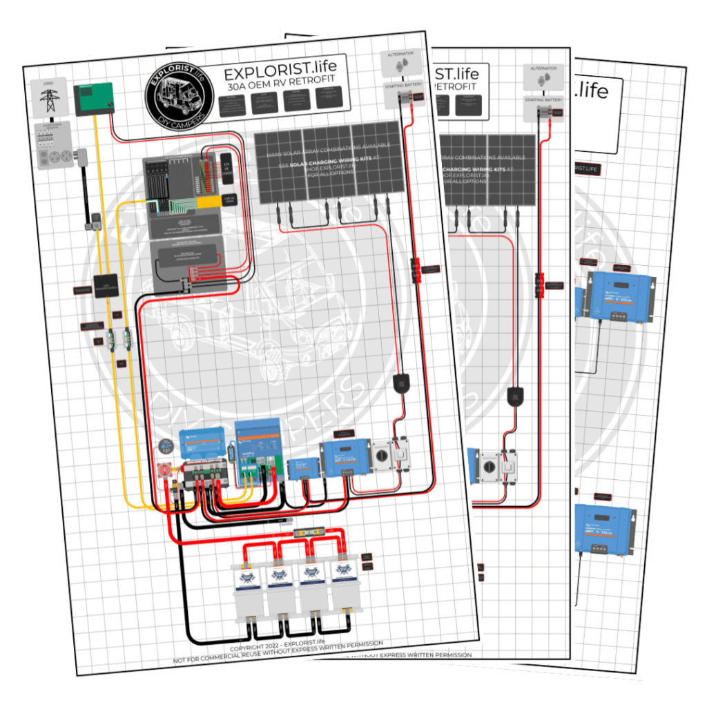
30 Amp OEM Camper Electrical Upgrade Wiring Diagram
30A Camper Solar Parts – Shopping List
The list below is a consolidated parts list for this entire system (Minus the solar charging leg, which is listed at the bottom of this blog post).
For the ‘Quantities’ in the below shopping list, each singular component is listed a quanty per each, wire is listed a quantity of feet, and heat shrink is listed as qty 1 = 2.25″.
For Example:
Qty 1 – Inverter Charger means you need to purchase 1 Inverter Charger
Qty 3 – 4/0 Wire means you need 3 feet of 4/0 wire. This may mean you need to buy 5ft from the product page
Qty 5 heat shrink means you need 5 pieces of 2.25″ heat shrink. This means you’ll need 5 x 2.25″ pieces of heat shrink for a total of 11.25″ of heat shrink.
30A Camper Solar Parts Detail
The section below will tell you where each of the parts from above fits into the wiring diagram. This is quite lengthy, but if you are having trouble seeing the diagram or just want more clarification that the diagram above doesn’t deliver, hopefully this will help:
Solar Charging Parts List & Wiring Diagrams
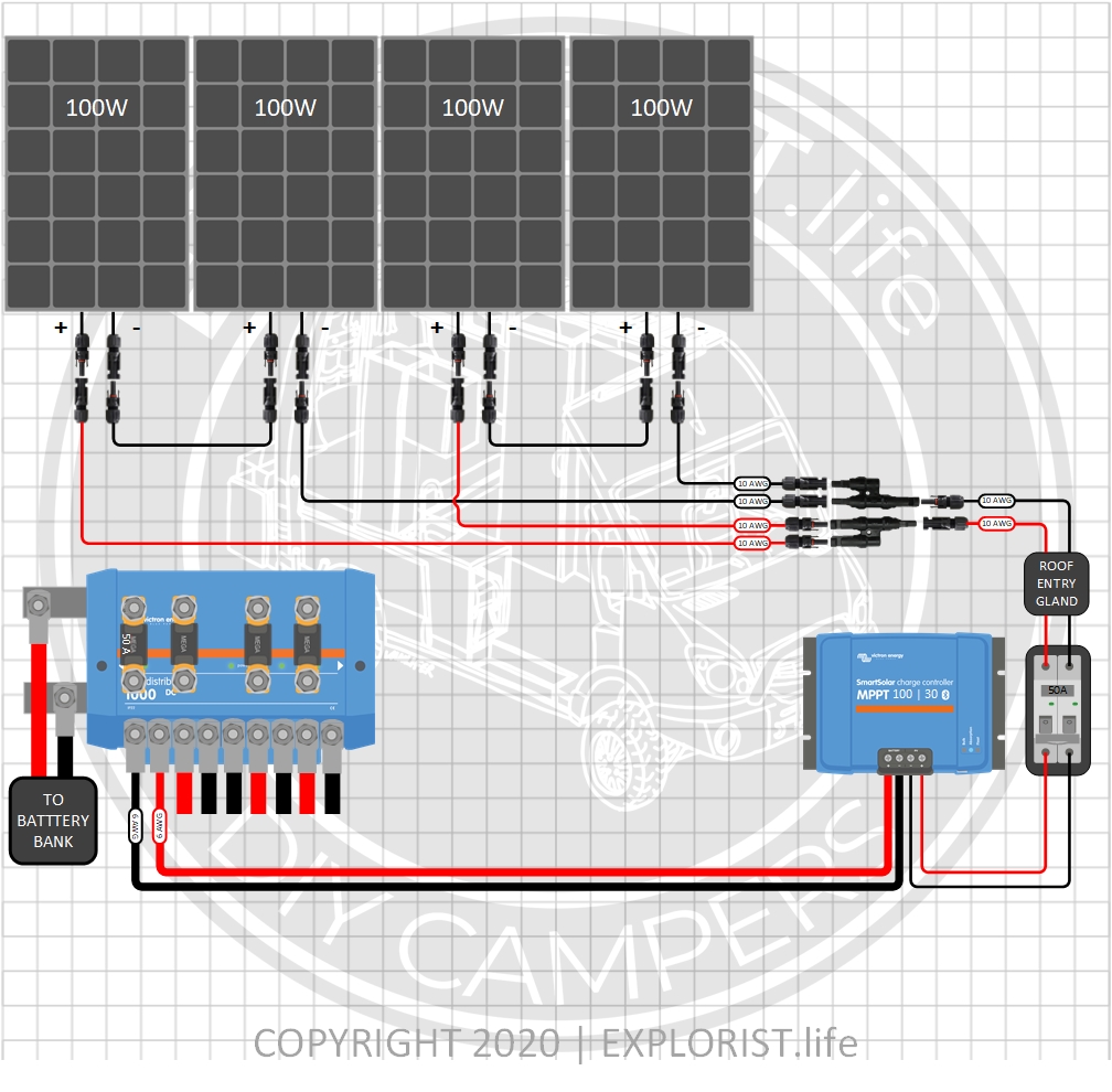
The following section provides you with several different options for solar charging. The above parts list can remain completely unchanged and the diagram above can remain mostly unchanged except for the alterations noted by the diagrams below, but whatever solar array setup you choose below for your needs, these parts will need to be added to your shopping list. These are broken up by total solar wattage. As a general rule, you want to have twice as many watts of solar as you do amp hours of batteries. So, 300Ah Batteries = 600W solar. 400Ah Batteries = 800W solar. 600Ah Batteries = 1200W of solar. This is just a rule of thumb. Not a law.
400 Watts – 4x100W Solar Panels – 12V Battery Bank (Click to Expand)
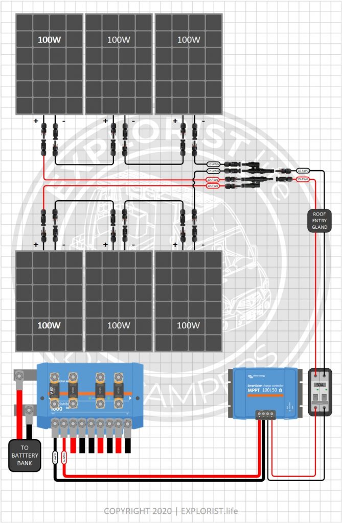
600 Watts – 6x100W Solar Panels – 12V Battery Bank (Click to Expand)
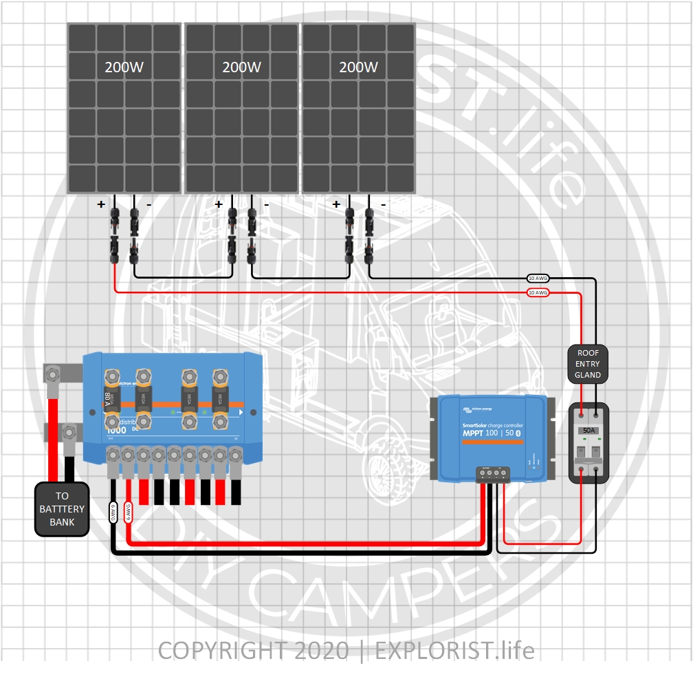
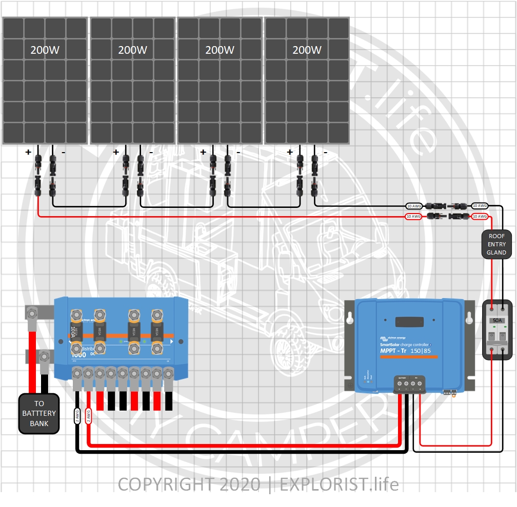
600 Watts – 3x200W Solar Panels- 12V Battery Bank (Click to Expand)
800 Watts – 4x200W Solar Panels- 12V Battery Bank (Click to Expand)
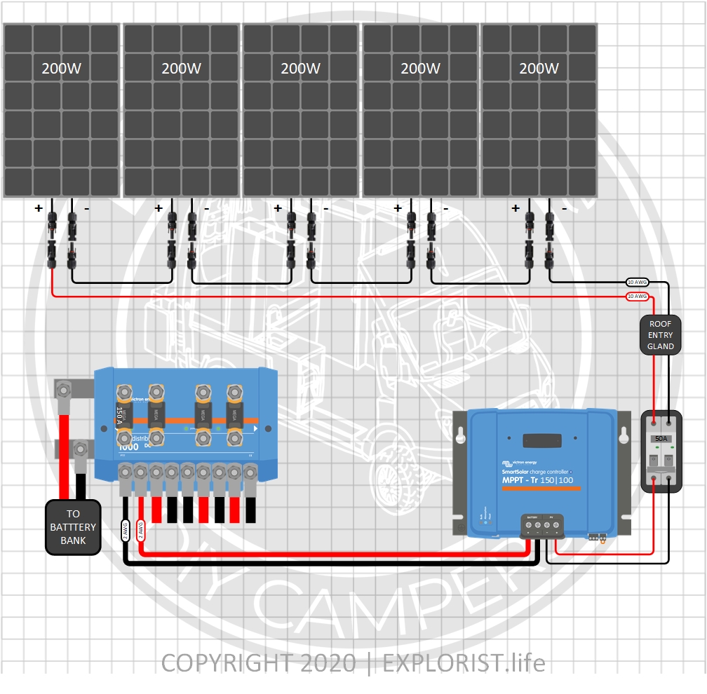
1000 Watts – 5x200W Solar Panels- 12V Battery Bank (Click to Expand)
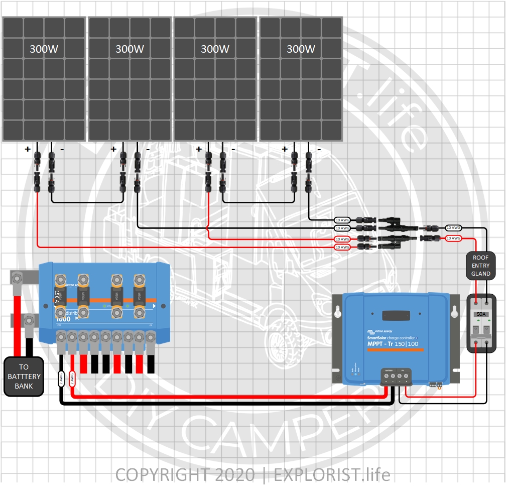
1200 Watts – 4x300W Solar Panels- 12V Battery Bank (Click to Expand)
Typical 30A RV OEM Wiring
Here is a quick look at how MOST stock OEM RV’s are wired:
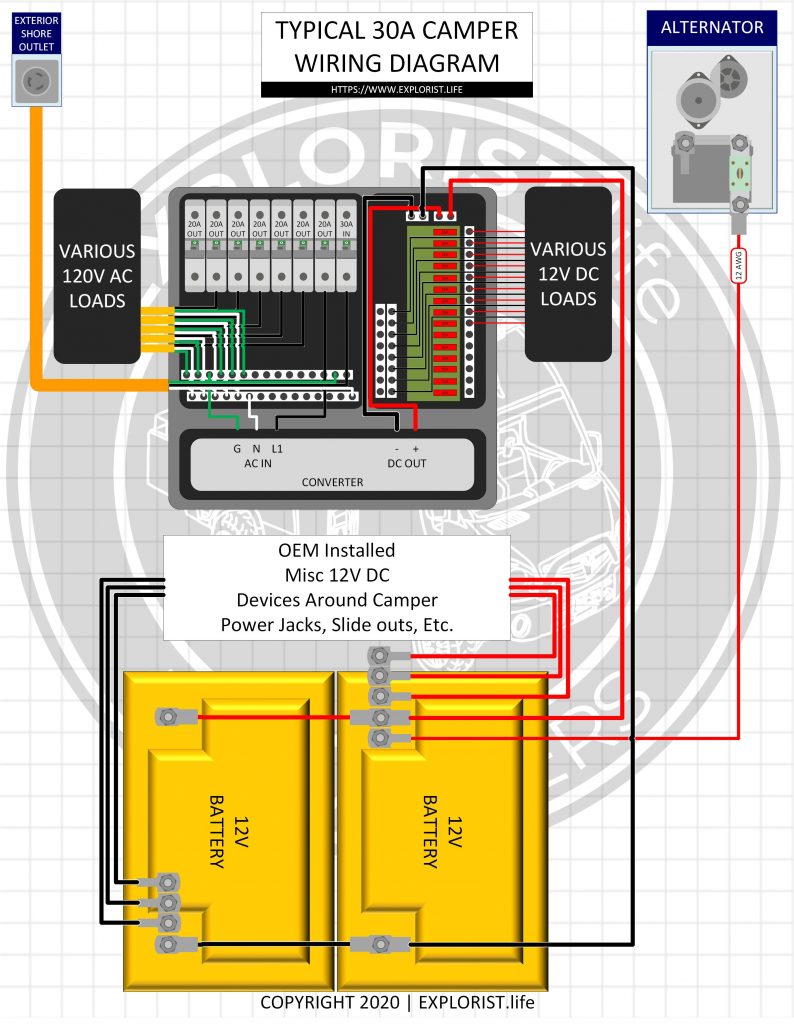
- The diagram above shows the typical bare-bones OEM RV/Camper with 30A shore power service.
- Shore power flows into the breaker box, powering the breaker box protected by a 30A breaker where 120V AC power is then distributed to the various circuits.
- One circuit is generally the Converter. The converter is usually built into the same enclosure that houses the breaker box (as shown) but is sometimes external. Either way, it’s wired in the same method.
- The converter converts the 120V AC power to 12V DC power which feeds the DC Fuse Block which powers the various DC devices around the camper (Lights, Fans, Etc..).
- From there, a positive and negative wire continues on to the house battery bank; usually two 12v batteries wired in parallel. These wires charge the batteries from shore power, and allow 12v devices to run when not connected to shore power.
- At the batteries, there are usually 2+ additional positive and negative wires heading off under the RV somewhere that are going to power additional DC circuits around the camper. These may be slide-outs, powered leveling jacks, and other ‘chassis’ items like that. These wires will likely have fuses in line to protect these wires coming from the battery.
- One of these wires is also likely the wire coming from the alternator to charge the house battery bank.
- When the camper is NOT plugged in to shore power, all of the 12V DC appliances will run due to them still being connected to the batteries, but the 120V AC appliances will NOT operate because the converter is a one-way-street and will not convert 12V DC back to 120V AC. The charging from alternator is typically very slow (less than 10 amps) and should, generally, not be relied on to provide adequate power for recharging deeply depleted house battery banks.
How to Integrate a DIY Camper Electrical Upgrade with the OEM Wiring
In addition to wiring the components together, here is a breakdown of how the flow of power to the above diagram works.
WIRING THE INVERTER/CHARGER To Shore Power.
When connected to shore power or generator, power flows from shore power (or generator) to the Victron Multiplus inverter charger. This charges the batteries which feeds the DC fuse block and allows 30A shore power passthrough to power the 120v appliances. You will take the 10/3 wire that goes from the shore power inlet to the back of the AC distribution panel and instead, run that wire from the shore power inlet to the input of the Victron Multiplus.
Wiring the Inverter/Charger AC Distribution Panel
The wire from the Multiplus Inverter/Charger to the AC Distribution panel should be replaced from the 10/3 OEM installed wire to a 6/3 wire and the 30A main breaker should be replaced with a 50A main breaker to accommodate for the additional capabilities of the Victron PowerAssist function.
Wiring the Solar Panel Array to your Camper Electrical System
When charging from solar, the solar panels & charge controller charge the batteries. The batteries are connected to the DC fuse block allowing use of the 12v devices around the camper. The Inverter takes the 12V DC power stored in the batteries and converts it to 120V AC power to power the 120V AC items around the camper.
Replacing Stock Camper Batteries with Busbars
A positive and negative busbar take the place of the stock batteries in the stock battery location (assuming that upgrading batteries means you will not be able to store your new battery bank in the stock location). From the Lynx Distributor, power flows to these two busbars where power is then sent to all of the OEM installed components like the DC distribution block, power jacks, slides, etc.
30A Camper Converter
The OEM installed converter must be completely disconnected. It can remain installed, but the wires must be disconnected from both the AC and DC side of the power distribution center. These wires can usually be bundled up and stuffed next to the converter.
30A Camper Alternator Charging
You will likely have a wire charging your OEM batteries from the alternator. This wire will likely be somewhere in the 12 AWG range. This will either run directly from your starting battery isolator if this is a motorhome or from your 7-pin connector if this is a trailer. This needs to be disconnected completely. This diagram uses a 30A DC-DC Charger and the OEM installed wire will be too small. The 6 AWG wire in the diagram will take the place of the OEM wire you are to remove. In the case of a trailer, 6 AWG wire will need to be run all the way to the truck starting battery if alternator charging via DC-DC Charger is desired and disconnected by the hitch by means of an Anderson connector.

131 Responses
Hi there,
Just bought the wiring diagram, but I have one (probably dumb) question: between the Entry Glan and MPPT unit the wires from solar panels connect through a box next to Solar Isolator with all lugs (these may be Phillips screws, but unlike on the MPPT, they look like plus signs). There is no identification for what this unit is or does. Does this represent the Isolator guts with the dial/box cover next to it?
That is indeed the inside of the isolator: https://shop.explorist.life/shop/all-products/switches-disconnects/solar-isolator-disconnect/
Just bought the diagram for this. It shows 10/3 going from the inverter to the distribution panel but the above says 6/3. The diagram should also be 6/3, right?
I’ve recently switched the diagram over to 10ga, which is the most up-to-date recommendation. Most 30A OEM RV’s have a breaker box that is only rated to 30A and upgrading to 6/3 wire to fully utilize the PowerAssist function of the Multiplus would require replacement of the breaker box, which I found most people did not want/need; so I’ve dialed that wire back to 10/3.
Hey Nate,
Love Victron components for their quality, system communication and the fact replacements are available worldwide. What about sailboats. Do you consult and design marine systems? Let me know.
Campers and boats are very similar, but I don’t have any full installs on boats at this time.
Bought the 30A OEM install diagram. I’d love to pay for a little consulting. I have the 110 and 12v oem schematics for the 2015 sprinter RV. We have Renogy equipment and batteries (bought prior to finding your sight). If I send the information on the renogy equipment and schematics of the rv, can you come up with an install schematic? As I said, more than willing to pay for consulting.
It would be a better use of your money to upgrade to Victron components instead of using Renogy + paying my hourly consulting fee to make a system. It would be cheaper to go the Victron route.
Nate thanks for the great info! I am installing a very similar setup to this wiring diagram on my Cirrus 620 camper and had a few questions.
1.) I plan on installing the Victron Cerbo GX and GX 50 Touch for monitoring. I was debating between the Victron Smart Shunt with BMV-712 or the Lynx Shunt without BMV-12. Do you have a recommendation for this setup?
2.) I am planning on using the Victron Inverter/Charger 3000. I have been deciding which batteries to use. I see that 400ah+ is recommended for this setup but I have been looking into the Lithionics 320 Ah battery as it is the perfect size for the battery compartment in the Cirrus 620 camper and can heat itself. From what I can tell the Lithionics user manual lists the battery as working with the Victron 3000. Do you think this battery will work with the inverter or do you think I should go with 400ah?
1: Either will be good given use of the Cerbo GX.
2: I recommend going with 400Ah or more of Battle Born Batteries.
This 30A retrofit is close but no cigar. My 2005 Airstream Sprinter has shore power, 12v AGM battery, alternator charging and a generator. It lacks LiFePo (lead acid) inverter/charger and solar. I want to integrate those into my existing system. Can you help?
I can definitely help! All of these tutorials and resources I’ve made available at https://www.explorist.life and youtube.com/exploristlife are designed to teach you how to design and install campervan electrical upgrades. Start watching and reading; take notes, do a bit of off-site study as well and you should be able to come up with a good plan on how to proceed and upgrade your system to your own needs. Hope this helps!
The diagram shows positive/negative runs of 2 AWG from the MPPT to the Lynx Distributor. This is physically impossible (even with ferrules) because of the spacing of the terminals on the MPPT. What am I missing?
Are you trying to connect to an MPPT 100|30 or 100|50? If so… the wire size should be 6 AWG. The 2 AWG in the big diagram at the top is for 150|xx and 250|xx charge controllers.
Hey. I have a question about the isolated B2B charger. I am going to use the 30A one from Victron and my van battery is 6m away from where we want to put the B2B charger. When doing the distance to and from the van battery and the B2B and putting it into your calculator it comes up saying that it needs a wire size bigger than the Orion can handle. Does this mean I need to move the Orion closer to the battery or do I only measure the distance from the battery to the Orion and don’t calculate the distance back?
Thanks,
Doug
Use the 6AWG. If there is ‘excessive’ voltage drop; the orion will make up for it (since the device is, by nature, a voltage booster).
Maybe this is a stupid question but what is the difference between a setup like this and using a Yeti 6000 goal zero portable power station for the whole RV?
I’m building a tiny house in a school bus and I am just now getting started on the electrical planning. I’m ripping out the floor in the bus right now so I have a bit of time before I need to have the electrical Figured Out.
Systems like these are a permanent solution meant to be built-in. Systems like the Goal Zero are great, but are more of a temporary solution. Sort of like building a detached garage for your house vs a $400 shed from home depot.
Hi Nate, love all your videos and blog articles. I purchased your 30A OEM RV Solar Retrofit Diagram to help along with your corresponding blog post. I am in the process of adding 800w of solar (4×200 RICH Solar panels), VE SmartSolar 100/50 MPPT charger, VE Multiplus 3000, VE Lynx Distributor, and I’m using 2 206ah SOK lithiums. I have ordered your Lnyx adapters and followed your other recommendations for all fuses and shutoff, etc. I am not adding a B2B charger at this time but may in the future. I have a few questions, if I may.
1. I bought the pair of Lynx Adapters but on the diagram it looks like a similar adapter is used on the ground connection for the Multiplus where the 4/0 ground wire from the Lynx connects and then sends off a 2awg ground wire to the MPPT charger. Do I need to order something for there or can I just attach both lugs on that ground post?
2. I’m totally confused by the Wiring the “Busbar to DC Fuse Block” section. I assume when you say “Busbar” you’re referring to the Lynx? I’m wondering why I need that? I didn’t run any wire for that because I did run a new 6awg wire from the OEM location on the trailer frame (where the original batteries where attached) to the Lynx. My assumption was that I was providing “new” power back to the original location via the new run of 6awg wire and the DC Fuse Block would then get it’s power supply as it did from the factory. Is this wrong? I’m sure hoping I don’t need to drop the belly covering again to run new wire.
3. Finally, I also don’t quite follow why I need to disconnect the charging wire from my truck via the 7-pin connector. What is new in my system that requires me to do this? Will something be damaged if I leave it alone? I’m just not understanding what this is all about.
Thanks so much for everything Nate. I watch all your videos whether they relate to my situation or not just because they are so interesting.
Paul
1: The two lugs on the equipment ground stud on the Multiplus are simply stacked on top of each other.
2: Correct (If I’m understanding you correctly). Busbar inside of the Lynx Distributor.
3: Nothing will be damaged; but the 7A your truck charges your camper at may ‘override’ the 800W of solar on your roof that could be potentially charging at 50a.
Hey Nate, Seems like your consolidated supply list at the top is missing some major components (like the inverter charger, the battery to battery charger). We went ahead and double-checked everything against the detailed supply lists, but thought you’d like to know.
Thanks for the heads up! Should be fixed now.
Hi Nate. Thanks for providing such a great resource. For the 30A camper retrofit, is there a max Ah for the 12V battery bank in the system? I would like to have 1000Ah. Should I be worried about this or can I go even bigger? Thanks.
There’s really no max. For a bigger battery bank like that, though, I would recommend using a larger battery like one of these: https://www.explorist.life/new-270ah-battle-born-lithium-batteries/ so you can use fewer batteries.
Hello Nate,
I have purchased your diagram for the 30A OEM conversion which has been very helpful! I have one question. I have a RV that has a generator that I would like to keep. I would like to be able to charge my new LiFeP04 batteries from either my new solar array, shore power or generator. I have read some about this & have found suggestions to add a 2nd transfer switch right after the existing transfer switch. The 1st transfer switch would choose between generator or shore power (as currently wired) then the 2nd transfer switch would chose between either of those or the inverter. The reason I would add the 2nd transfer switch is so that I can never have more than one source charging the batteries at the same time. Does this make sense? If not, is there a better way to set this up?
What, if anything would I need to change other than wiring in the 2nd transfer switch?
Thanks for your help!
Cindy
If you simply wire it as it is shown in the diagram, your system will have the functionality you described.
@Nate Yarbrough, so you’re saying I don’t need the 2nd transfer switch? I don’t see anything in the diagram about the generator. Should one of the inputs to the OEM transfer switch say generator? Both sources say exterior shore outlet on the diagram. Thanks!
Oh, I see. Yes… one of the shore power inputs would be your generator.
Collected some data today:
I got the voltmeter out and took some measurements. With 140 A of current draws, the 4/0 cables that run from the batteries and to the inverter had voltage drops of about 0.05 V each. My calculations based on the wire gauge and length say it should be about a tenth of that, but I don’t know what to expect for connector losses. Thoughts?
For a 12V battery bank, that’s something like 0.3%, which is really low. Nice work!
Nate,
Thanks for all of the work you have put in on the various platforms. I bought and used the diagram from this post to put together my system and it has been working great. Today I opened up the battery compartment to add in the wiring for the generator and decided to run the A/C for a while. It ran for about an hour drawing 110 Amps and the battery cables got really warm. The shunt and other terminals were hot to the touch. Do you think something is wrong or is that to be expected at such a large current draw?
They shouldn’t be so hot you can’t touch them, no. Excessive heat build up is usually a result of a bad crimp or a loose connection. Go back and verify that ALL bolts and terminals in your system are nice and tight.
Nate,
Any chance of covering tying in a generator with a transfer switch to a solar charging system like this?
Sure! There is a transfer switch in this diagram for that purpose.
Hey Nate, love the content. I purchased your wiring diagram for Andy’s Airstream and used it as a roadmap for my upfit in our Keystone Hideout. Also purchased a set of your copper bus bar connectors. Everything with the install went well although I’m having an issue with my Multiplus 3000. It functions as expected for everything except charging. When I plug shore power in to charge the batteries it toggles between charging and inverting every 10 seconds or so. It has to be a setting I’m missing somewhere but I can’t seem to figure it out. The only thing I haven’t installed yet is the equipment ground and solar panels, neither of which I can see causing this. I found 1 thread similar to this on Victron’s community page but the issue never seemed to be resolved, at least not in the published thread. Any ideas?
I haven’t yet run into that issue. I could see a loose connection doing that though. Or perhaps a wire going to the wrong spot in the multiplus or the breaker box. That’s where I would start.
Nate,
I bought and use your diagram to build and install my system.I installed everything but the Orion. Everything works great!
But I am having a problem that I don’t understand. When I am plugged into shore power and use a high drew item like the microwave (12.5amps) or air conditioner I am getting a low battery, battery voltage ripple, and sometimes an overload warning from the Victron App.
It’s strange because I don’t get any warnings when high draw items without shore power, everything seems to work fine when the power is coming from the batteries through the inverter.
At first, I thought maybe the shore power source may have not been providing 30amp’s and the inverter was kicking in to make up the difference. But it is happening anywhere I plug into a 30amp service.
That’s really strange. It makes no sense why you’d get a high ripple warning when on shore power but NOT when only on battery power as DC ripple only happens when the source of power is a battery. Make sure your ‘shore power input limit’ for your multiplus is set 2-3 amps lower than whatever amperage of shore power you are connected to. After that, I would dive into the connections and quadruple check all of your wired are wired in properly, as you could have a neutral going to the wrong place, which could give an unexpected result. Lastly, If you suspect something is actually wrong with your inverter, I’d recommend reaching out to the place you bought it from for additional tech support and a warranty replacement if necessary.
@Nate Yarbrough, Problem solved. I got with Battle Born batteries and Brendon help me correct a few settings that weren’t correct and now everything is working as expected. Including the shore power limit as you mentioned above.
I’m upgrading my travel trailer in stages (the info you’ve provided has been invaluable). I’ve complete the install of the multiplus and battery bank. Later I’ll be adding solar and alternator charging. My question is, do I need to disconnect the 7-pin 12v power from the bus bars that replace the OEM batteries now? I’m not expecting much (if any) charging from the tow vehicle, just wondering if it could cause damage if left connected. Thanks
You can leave that connected for now. That’s fine.
Hey Nate. In your instructions you mention upgrading the input A/C breaker from the OEM 30amp to 50amp….My panel shows that it is rated for 30amp. Is it ok to add the 50amp breaker?
If that’s the case, leave the 30A breaker as-is and also downgrade the 6/3 wire to 10/3 (same as what’s already there).
@Nate Yarbrough, I’ve already installed the 6/3 wire under the floor per your 3000w inverter diagram and don’t want to rerun 10/3 wire. Can I use the 6/3 wire with a 30A main control panel breaker and limit the current coming from the MultiPlus 3000 inverter charger?
If it will fit into the breaker and busbars, yes, that’s fine.
Since you recommend using the Orion in place of a BIM, I’m wondering how the starter battery can be charged when not being driven for long periods of time? Since the Orion removes the Aux Start button – I’m thinking there may be a need to keep the starter battery charged.
The Multiplus has a starter battery charging circuit built in. It will charge at something like 2A to keep the starter battery charged. It won’t jump start, but it’ll keep the battery charged. You’d want to add a seperate solenoid isolator circuit for emergency jump starting if desired.
I have a KZ 271bhse travel trailer that I recently upgraded to a set of 6v EGC2 230AH batteries. I want to upgrade the converter/charger also to a 3 stage. I plan on replacing the line from the battery to the fuse box with 4 AWG wire (currently 8 AWG, 27’ long). I cannot find any info on the factory converter but it goes into a 15A breaker. If I install a 35A smart converter/charger will I just need to put in a new breaker for it since I’m already upgraded the line from the battery? I’d like to upgrade this because I also plan on putting together a 200w portable solar suitcase for when I’m hunting so I don’t have to use the generator unless I have to.
I’m not fully following your plan, but a 15A AC breaker to power a 35A converter is fine (on the AC side of things). A 15A DC breaker protecting the wire from the batteries to the converter would be too small for a 25A converter and a larger breaker would indeed be required.
Where does the 60 Amp Terminal Fuse go in the above diagram?
Thank you,
Holly & Dustin
That is attached to the starter battery.
I plan to upgrade my 2015 Fleetwood Storm 28MS based on your excellent information – but I have a question. You mention disconnecting the existing AC-DC charger that is in the breaker box – but what about the AUX battery disconnect switch/solenoid? It would be nice to be able to keep this so we can disconnect the house batteries while storing.
Your diagram doesn’t seem to have any type of disconnect other than the solar breaker. Is it not necessary to disconnect when storing?
Master battery disconnect would go between the battery bank and the Lynx Distributor.
Hi Nate, thank you for the extremely informative videos! I just purchased your DIY Campervan Solar Setup pdf, and have a question I hope you won’t mind addressing. The Orion DC/DC shows 6AWG from the alternator/vehicle-battery, and 6AWG from the Orion to the Lynx, but the graphic depicts different size wires (different width lines). The reason for my question is that the distance from my vehicle battery in a Sprinter van is approx. 13.5′ (27′ round trip) to the house batteries. In my scenario, I would like to locate the Orion close to the vehicle battery (far from the house batteries) to facilitate wiring an audio amplifier to take power from the vehicle system when running, or the house batteries when camping. Essentially, the amp gets power from the vehicle side of the DC/DC charger when the vehicle is running, or on the house battery side when camping. Finally the question….
1. 6AWG just barely clears the 3% voltage-drop hurdle for 21′ (Orion mount to house batteries). Is that distance ok for the Orion-to-house-batts? Is the voltage drop more critical on the house battery side of the Orion? Can it be managed?
2. I’m planning to parallel two Orions. So, according to your diagram and wire size calc., I would up the wire to 4AWG to handle 60A.
3. Finally, the amplifier is fused for 80A/12V, so the 3% hurdle requires 1AWG (total round trip run of 35′). So, this becomes the limiting wire size. Going back to the wire size calc., this size cable would provide for no more than 1.5% voltage drop for the Orion-to-house batteries run. Does this change your answer to #1. Or, do I need to mount the Orions close to the house batteries and deal with another cable run?
Thanks, very much!
Ed
I would HIGHLY recommend installing the Orion near the House battery bank. This will overcome any kind of voltage drop from the starter battery to the Orion.
With dual Orions… the ‘most straightforward way’ is to, essentially, copy paste the charging leg and just use 2x 6 AWG wires to power each orion seperately.
I would then run a dedicated wire to the amplifier. It would be a lot of wire, but would be the most correct way to do it.
Hey just wondering. Is it possible to use this set-up with a second array of solar panels/charge controller?
Yep! Here is a tutorial for wiring multiple charge controllers: https://www.youtube.com/watch?v=N0UB7LZVduk
Nate, love the content here – downloaded the PDF, and I’m looking to put an order together. I’m looking to do this install with a slight reduction in solar (~400W) and battery (200Ah), with the possibility of adding another 100Ah battery later. Would you recommend any changes given this scenario?
The Multiplus 3k requires a minimum of 400Ah of battery capacity. If you were going with only 200Ah of battery capacity, you would have to use the Multiplus 2k. The wiring would be similar, but the wire sizes and fuse sizes would be smaller. Example: https://www.explorist.life/2000w-inverter-200-400ah-lithium-200-to-700w-solar-camper-wiring-diagram/
Nate,
Do you see any issue using this system with 6V Royal batteries in series to 12V? I am going this route because our bus has the weight capactity and room to handle the extra size.
Given you you properly wire your 6v batteries into a 12V battery bank, this setup will indeed work.
Hi Nate . I have am using a All Aluminum Cargo trailer and using this 30A OEM RV Solar Retrofit Diagram in my build . I have all the Victron equipment and are wondering where to ground to the Chasse since its all Aluminum ?
And can I use three 24 volt batteries instead of the six 12 volt in your diagram ?
Andy solidly mounted metal to frame connection will work for the chassis ground.
You cannot use 24V batteries in this system.
Hi Nate. I have a TT with the batteries on the tongue. I’m upgrading the batteries to LiFePO4 and moving them to the under bed storage. The rest of the components in your diagram will be installed in the passthrough. The under bed storage and passthrough are next to each other. From the tongue the battery positive and negative wiring go to a junction under the trailer just behind the tongue. In the junction the positive cable connects to a fuse and continues to a master disconnect switch and on to the DC panel. There are two more fuses in the junction box powering the jacks, exterior lights, etc. There is a jumper wire from the positive battery fuse to the other two fuses. Within the junction are all of the ground wires. My question, using your components and wiring diagram do I need to keep these fuses in the junction box or can I replace them with busbars and rely on the fuses in the Victron Lynx Distributor. Thank you.
The fuse in the Lynx Distributor would protect the wire to the factory battery bank location. From there… It’s up to how the RV was manufactured, so if it needs additional fuses… I would have hoped they were installed from the factory.
Nate the renogy panels u recommend are 300w 24V panels but the Victron charge controller and inverter/ charger is 12 volt. I thought with a 12v battery bank the solar panels would need to be 12v. Can you clarify this please.
This should help: https://www.youtube.com/watch?v=6G3Mo_OHmQY
Nate, what’s the max length the between (4 BB) batteries and the Victron Multiplus Inverter Charger 3000 W 12 V? To fit on the TT the best I really need to separate them by 15ft or so. Is that too far?
Thanks
15ft from batteries to the inverter is indeed too far per pg. 8 of the Victron Multiplus user manual: https://www.victronenergy.com/upload/documents/Manual-MultiPlus-3k-120V-(firmware-xxxx4xx)-EN.pdf
@Nate Yarbrough, that’s a bummer. Time to reconfigure :). Thanks
Normal Voltage Drop
Under a load of 130A, I have a voltage drop of about 0.4 volts from battery bank to multiplus inverter. Normal?
The battery bank was at 12.4 volts and the inverter at 12.0. The respective voltages (from inverter tracing back to battery bank) were: 12.00 at inverter, 12.10 before Lynx Distributor, 12.13 before on/off, 12.30 before ANL fuse (biggest loss by far) and 12.4 at bank.
Under progressively heavier loads my inverter shut down due to the low voltage cutoff (currently at 11.5).
12.4V to 12V is 9.6% voltage drop is at the high end of normal (Anything under 10% is acceptable), but it’s still higher than expected (I would expect under 3%) for this system. I would recommend going back and checking each and every bolt in your system and making sure they are all tight and that you do not have any loose connections.
Also, seeing as the biggest voltage loss is at the ANL fuse… Just verifying… but you are using high-quality Blue Sea fuses & fuse holders as specified in this diagram and parts list, correct?
@Nate Yarbrough, currently I have a “Boamain” fuse installed (probably junk) and am waiting on Amazon to deliver my Blue Sea ANL Fuse (400A). Hopefully that fixes the voltage drop across the fuse.
I will double check all other connections.
I would be willing to bet that fuse is 100% the problem. Those no-name fuses and fuse holders have been giving SOOOO many issues this year which is why none of my parts lists utilize those inexpensive ANL Fuses. More info under the “Cheap vs Expensive Fuses” heading here: https://www.explorist.life/best-fuses-fuse-holders-for-a-diy-camper-electrical-install/
Make sure you have a Blue Sea fuse holder as noted in the parts list in addition to the Blue Sea ANL Fuse you said you ordered.
@Nate Yarbrough, Baomain fuse = 100% of the problem. There is zero voltage drop across the Blue Sea fuse and now my system does not hit the low voltage cutoff under heavy load. Thanks Nate!
@Nate Yarbrough, also, yes I am using the Blue Sea fuse holder as recommended (and also used the high quality 4/0 cable and terminals you recommended).
Nate, Thanks for all the great information. I purchased one of your wiring diagrams for an 30amp RV set up. I am going to start with 4 BB 100 amp hr batteries and 4-6 solar panels. And after looking at your site and many of the videos I am understanding most of the install. I am having trouble understanding where the Victron Orion Smart 12|12 – 30A wires to on the vehicle battery side. Does it just connect into the trailer 7 pin wiring harness that connects to the truck?
That needs to actually be connected to the starting battery of your vehicle. Yor 7 Pin connector likely only uses 12-14ga wire, which is too small for this increased load. Make the connection for the new 6 AWG wire from truck to trailer with an anderson connector: https://amzn.to/3bpUUJL
@Nate Yarbrough, Thanks, I think I may leave that out to start with. Then see if I need after I use it for a while.
Thanks for all your content, Nate. Its simply awesome!
Few questions:
1. Grounding: my 30A travel trailer already has grounding at the breaker box (presumably it leads to chassis). I installed a full inverter/solar system following your diagram and grounded the Lynx Distributor directly to the chassis with 4/0. Do I need to remove the original grounding points at the breaker box, or is it okay to ground to chassis at multiple points?
2. Alternator charging: I have a traditional 7-pin connector that I believe provides minimal charging from my truck alternator to travel trailer while driving. My system does not include an isolator or additional alternator charger (it looks identical to the system you installed in the Airstream). I don’t need alternator charging, but I just want to ensure my setup will not damage my truck alternator. Do I need to add any protection? Or take any steps to isolate the truck?
Thanks Nate!
1: There can be multiple DC grounding points.
2: It would be best to simply disconnect the alternator charging wire from your battery bank in that case.
@Nate Yarbrough, any recommendations on how to identify the alternator charging wire?
Use a multimeter to check for a wire that has voltage when the engine is on vs off.
@Nate Yarbrough, good call. As always, thanks so much for the help. Where should I post some pictures of my final system that I built using your wiring diagrams?
You can tag EXPLORIST.life on Facebook or Instagram or you can send them to me by email if you wish. 🙂
@Nate Yarbrough, great, I’ll send some over.
Nate,
Great job with the website and providing kits for power system installs. I have a question regarding the Victron Multiplus 3000 boosting inverter. Once or twice a month (we leave the inverter running almost constantly), the inverter will buzz very loudly. I have tried shutting off all the AC breakers, one by one, to see if it will stop and that has no effect. Turning the inverter off and on from the Victron Multi Control stops the noise while the inverter is off, but the buzzing noise starts back up when the inverter is turned back on. The loads on the inverter are very low when this occurs. Normally the inverter hums a little when under load, but the buzzing is very loud and annoying. It tends to go away on its own after 20-30 minutes. The installer said that happens with non linear loads occasionally. Below is a list of components for my installation. Have you run across this ever? Thanks for your insights.
Component List
400Ahrs Victron Lithium batteries 2-200Ahrs connected in parallel
3000w Victron Multiplus boosting inverter charger (all AC loads pass through the inverter)
720w roof mounted solar 4 -180w panels connected in parallel
50a Victron charge controller for the solar panels
Victron Color Control panel
Victron Multi Control remote inverter controller
Victron BMV-712 Smart Battery Controller
Nations 280A Alternator and Balmar voltage regulator (4000W Onan generator was removed)
AM Solar Battery Management system
Something definitely sounds wrong with the inverter. I would recommend reaching out to the place you purchased the Inverter from and see if this may be a warranty replacement issue or something. The inverter will buzz under certain loads, yes; but should stop as soon as the load is turned off. For example… my heat gun when on the ‘low’ setting makes the inverter make noise; but as soon as I turn the heat gun to off or ‘High’, the noise goes away.
Hi Nate, I am installing the Orion DC charger and have the 6awg wire and fuse coming from the alternator/starter battery. My question is, the oem setup used a 2awg positive wire to an isolator/relay and had ground wire that just went to the frame. In all of your diagrams, you have the positive and negative ground wires coming from the starter battery into the Orion charger. Do I need to run another 6awg wire from the starter battery negative terminal to the Orion or can I just run a negative wire from the chassis, and use the same ground as the lynx, inverter, mppt, etc?
Nate,
Thanks for making these super informative videos. You’re giving me hope that I’ll be able to knock out a Inverter install in the Spring. I was wondering if there were any requirements/minimums on distance between main Fuse and Battery Disconnect Switch. I know that Battery and Fuse need to be as close together as you can make them but I have not seen or heard anywhere if the disconnect switch should be or needs to be close to the Fuse. My current plan has 2-3 100ah BB Lithium Batteries wired to fuse in the tongue box of small travel trailer with cable running 7-ish feet to Batt Disconnect Switch on interior of trailer. I’m wondering if I need to rethink this.
There are no rules for switches regarding distances; only fuses.
Ok, searched why use ferrules on you tube and guess who has a video about that.
https://m.youtube.com/watch?v=h8CHAVmpPFw
Maybe my other questions will be answered as well.
Thanks!
Thank you Nate for all your hard work providing this information to us!
I noticed you spec the use of ferrules in some of your applications like the 6awg used in DC/DC charger applications.
-what is the purpose of these ferrules?
Does it avoid crushing the individual wire strands in the charger side of connection or make a better connection?
-Are these ferrules crimped?
-Will a hex and punch crimp both work?
I like the crimp tool you spec’d due to the different thicknesses found in lug terminals. It’s out of stock until end of month.
Temco stated the pinch crimper avoids loose connections that hex styles might make if lug thickness is undersized for the dies.
-Are both pinch and hex styles ok or should I postpone my install and order the hex model you recommended?
Thanks again!
What is a ferrule (and how to crimp one): https://www.youtube.com/watch?v=h8CHAVmpPFw
Either the indent or the hex crimper will work fine for lug terminals.
Hi Nate,
I was planning to run new 6 awg pos and neg wire from the Lynx distributor to the 12v side of my panel as per your diagram. However, I already have 8 awg going to the panel from the factory. The 8 awg pos was connected to the pos battery terminal and then went to several small bus bars before heading to the panel. The neg wire went from the neg battery terminal to the frame. So only the positive went all the way to the panel. This is how Forest River wired it. I am planning on disconnecting the converter/charger. I am not adding any new 12v loads and this old set up has worked well for 7 years. Can I just hook the 8 awg pos wire that was connected to the pos battery terminal to the Lynx and use it to feed the the small bus bars and the 12v side of the panel like with the original set up? The Lynx will be grounded to the frame. The panel is grounded as well. Thx
If I understand correctly, your proposed solution should work.
Thank you! One other question. I have been buying per your list, what do the 4/0 3/8 inch lugs go to? I see there are just two in the whole list. Thx
Mike
Master Battery Switch & Shunt.
Good day Nate, I was looking over this diagram and was curious why there isn’t a master disconnect between the battery bank and the Lynx distro?
Thanks for all you do
There should be. Oversight on my part. It made it into the parts list but not the diagram.
Thank you for making this resource available. Downloading this schematic is the best $10 I’ve ever spent. I am looking to retrofit a 30A travel trailer per this spec, but I notice you still show a 30A AC distribution panel in the plans. You show the 6/3 wire feeding the panel from the multiplus and I know from watching the Airstream upgrade video this is to leverage the power assist. However, if the power assist kicks in, won’t the 30A breaker trip? I was considering upgrading to handle 50A (just the single phase of shore power plus the power assist), but prefer not to replace the whole distribution center. Do you think the bus bars in a WFCO WF-8955 will handle 50A from the multiplus when supplying power assist if I just change the breaker?
Also, I’d like to include the Orion 12/12-30 charger. I’m putting the batteries, MPPT, Lynx and multiplus under the bunk in the rear of my travel trailer, closer to the power center and to lessen weight on the tongue. My tow vehicle battery will be about 42 feet from the Orion if I put it close to the multiplus, which I want to do to avoid voltage drop from the Orion to the multiplus. Of course this will mean pretty significant voltage drop from the tow vehicle to the Orion of about 7-8% over 6 AWG wire. Is that amount of voltage drop going to materially decrease the Orion’s performance or do you think it’s still a useful option?
Thank!
If the max ampacity of the breaker box is 30A and you do not plan to upgrade… you can use 10/3 from multiplus to the breaker box. Do not install a 50A breaker in a 30A breaker box.
Nate,
Thank you for what you do Sir.
I am going to use your 30A OEM RV retrofit wiring diagram(which i purchased) on my 28ft Grand Design 2250RK travel trailer , and get the necessary items off your awesome parts list links. I found your site after i bought most of the major items in your diagram from Battleborn Batteries on their Black Friday deals. Battleborn recommended i get a Lifepro Battery Isolation Monitor, which i do not see in your wiring diagram. I do see the Orion TR Smart isolated DC-DC charger.
1. Should i send back the BIM and purchase the Orion? I’m thinking yes.
2. I only plan to have the 7 way plug plugged in when i’m driving, so do i really need either of the components(BIM, or The Orion)?
3. I’d really prefer to get portable panels. I am starting off with 400ah of batteries, and probably adding 200ah more in the future. do you have any portable panel recommendations?
I drive a GMC Duramax that came with 2 batteries and a high output 220 amp altenator.
Thank You,
Brian
P.S.
Parts I’ve ordered on Black Friday
4- Battle Born 12v 100ah Batteries
1-Victron Multiplus 3000w
1- Victron BMV-712 battery Monitor
1-Victron Lynx Distributor
1- Victron Smart Solar 150/70 TR charge controller(Your diagram has the 150/100) i hope i’m good.
1- 225amp BIM Li-on Battery Isolation Manager
Part i ordered from your site
1- Lynx Adapter
1-Schematic 30a OEM RV solar retrofit wiring diagram
1: I would indeed recommend the Orion over the Li-BIM. ESPECIALLY in a tow-behind scenario as you will need to run new wire ALL the way to your starting battery. The 6 AWG for the Orion will be much more manageable than the 2/0 needed for the Li-BIM.
2: If you do not want alternator charging… you do not need either the Li-BIM nor the Orion. The 7-pin connection will likely not charge your batteries all the way to full though… More info: https://www.explorist.life/how-to-charge-diy-camper-van-batteries-with-vehicle-alternator/
3: Any panel can be a portable panel. 🙂 I don’t recommend any ‘portable specific’ panels. I would just advise getting normal panels and making a simple lean-to stand for them.
Hi Nate,
– Can the Newpowa 100w solar panels that get mounted with Z brackets be removed once installed without removing the brackets? I need to ship the RV on a ship not inside a container and I would like to remove the panels for save keeping.
– You have 6 batteries on the buy list, I spoke to Battle Born previously and because of space (19′ camper) and $$, I believe they suggested a minimum of 3 or 4 batteries, why is your system done with 6?
– I wanted to wire the a/c to work only with shore power since my original design system with 3-4 batteries won’t be enough to power it and I can generator power the a/c when necessary? Would that be considered a custom wiring diagram from you? If yes what’s the add on charge after I get the original diagram?
– With 5-6 batteries, will I be able to power the a/c?
Thanks so much.
1: Sure! Just plan for it when bolting it all together.
2: It is just a common size of battery bank that was requested. For this setup, you can use as few as 4 batteries. With 3 batteries… many things in this diagram need to change.
3: You could wire the AC OUTPUT 2 on the Multiplus to the side of the breaker box you wanted to run on shore power only. That’s what AC OUT 2 is for.
3b: I am currently not offering custom wiring diagrams. Sorry about that!
4: For a little while. You should do a power audit to see for how long it woud work: https://www.youtube.com/watch?v=a406IxiU-Xg
Hi, Nate. I’m building a 30A replacement system right now and using your diagram as a guide.
Where do you recommend hooking up the existing generator starter motor? Right now it’s an existing 2GA wire in the battery bay.
Lion Energy says it’s ok to hook the UT-1300 batteries to the Onan QG4000 generator but Onan only specifies the size of the wire, it does not list a fuse requirement.
I was going to connect the generator starter just after the 400AMP ANL Fuse in the diagram. Good idea or bad idea?
Also – what’s the best way to charge the chassis battery? I have the Orion to charge the lithium house batteries but what’s the best way to charge the chassis battery since I will be disconnecting the “boost” start relay since it’s a “dumb” relay.
Thanks!
In this diagram… the generator would be connected to the “Busbars in the OEM battery Location”; Just like everything else that was connected to the OEM batteries in their original location.
Nate, wondering about the chassis ground coming from the Solar Charge Controller. Since everything is tied to the Lynx Distributor, isn’t everything eventually tied to chassis ground. I am just barely learning about the DC side of things so my knowledge along these lines is very sparse.
The equipment grounds for the Solar Charge controller & Inverter/Charger are required by ABYC and are there so that in the case of catastrophic equipment failure & the positive wire touching the case of the device, the circuit will complete, short circuit, blow the fuse, and cut power to the circuit.
Nate,
Thank you so much for all of your info you have provided. It has helped us build our knowledge so easily. We are looking at creating a solar array for a 50 amp stationary trailer. We want to have a power station that we could plug in to the RV, and be able to essentially pull up to the power source and plug it in. Wondering if this plan works and would really appreciate your advice. Instead of wiring the inverter to the RV breaker, could we wire it to a female 50A outlet? Then use a 50A cord from the outlet to the RV. Thanks for your help and consideration!
This diagram will not work step-by-step for 50A service. It is made for campers with 30A shore power input. Perhaps I’m misunderstanding what you are trying to accomplish though; but I doubt this diagram will help with what you are trying to do.
Right, we are grasping ideas from this but trying to come up with a wiring diagram that would work for us. We are hoping to create a power station that we could plug our RV into rather than wiring everything in to the trailer itself. Are you going to open up 1 on 1 consults any time in the next month or two by chance?
Likely not. The best way to get my help is my private group: https://community.explorist.life/
In lieu of the 6/3 marine cable at ~ $6/ft, would 6/2 w/ground cable at ~ $2/ft work? I need about 25 feet… Thanks for the heads up on the Multiplus potential for additional 120v amperage.
You would have to cross-reference the cable you are hoping to use with ABYC standards on how many strands are inside of the wire you are proposing and see if that particular wire meets those particular codes. That can be found under ABYC E-11 Table XI.
The stuff from home depot/lowes will not be compliant. If it were… I would just recommend that stuff since it’s significantly less expensive. I assure you…I don’t recommend stuff just for the sake of it being expensive. There is generally ALWAYS a code compliance reason or a performance benefit.
Greeting Nate!
I’m hoping that you can shed some light on a installation that I’m trying to do. I currently have an 89 Fleetwood Jamboree RV that I’m incorporating solar into, but i’m wanting to run a 24v system. I currently have 400w of panels, a MPP Solar 2400w 24V 110Vac Solar Inverter + 60A battery charger + 80A MPPT solar charger (all in one unit) that will be tied into a 24v 2.45kWh (92.8Ah) A123 LFP Battery Box. Here comes the tricky part. I’m still running a 12v onboard system, and was wondering if I can still utilize both the 12v onboard, and the 24v solar. I wanted to do as you mentioned by running the A/C shore power to the MPP inverter charger, and then onto the input of the A/C distribution panel. I just don’t want the 24v solar system to charge the 12v batteries, nor do I want the alternator/12v system to interfere with the 24v system. Is this possible? Any help is greatly appreciated! Regards…
Sure! You would just have to use 12v-24v and 24v-12v converters in the places you were needing to make that conversion or keep the voltages isolated.
I’ve learned so much from your articles, and this one in particular was exactly what I was looking for! I had the general picture correct but it is reassuring to find that you landed in the same solution, and to get a better grasp on wire sizing.
Thank you so much for your hard work putting all this together
Hi Nate. I was wondering if you ever design a system that runs off only 300 amps of lithium batteries using the stock sprinters alternator
As of now, ALL of my diagrams found at https://www.explorist.life/solarwiringdiagrams can run off of 300Ah of Lithium batteries and the stock sprinter alternator.
Nate, which is the video where you connect the lynx -in to the lynx distribution and and diy the shunt in between the two? I watched it once and now can’t locate it. Appreciate it
That’s not a video I have out just yet. It’s coming, but the one you watched wasn’t from me. 🙂
Nate, I am installing a 50amp inlet to my camper. Do I change the cable (10/3) to my 3000 w Victron inverter charger to 6/3 to accommodate 50amps?
Or is the 10/3 enough to handle a 50 amp charge?
You’ll need to change ALL KINDS OF STUFF. 50A shore power is 240v split-phase. In order to make the change from 30A 120V single phase to 50A 240V split phase, you’ll not only need to change most of the wire sizes and fuses, you’ll also need to add a SECOND inverter to take care of the 2nd hot leg in the system. Unless you REALLY REALLY need that, I’d highly advise against it.
Nate, My 5th wheel came with 50 amp shore power and I’d really hoped to add solar at some point. Would you advise against that?
Adding solar is a great idea to any size of RV. 🙂
Thanks Nate, thats a relief. But the process does sound more complicated handling the 50 amp shore power. Is it a question of the input? What if I only rarely plug into 50 amp power?
thanks again,
stay safe, (Winter Park rocks!)
It’s a matter of having 2 x 120v circuits coming into the camper. 50A service is 240v split phase and consists of two 120v circuits.
Good Morning Nate,
Read your post regarding putting a dc-dc charger on a already built out van yesterday. Wow, a ton of great information. Thank you for doing what you do. I learn from each post.
My scenario is slightly different. I have a 2105 Pleasure Way Plateau on a MB 3500 chassis. I have 1 BB 100 AH battery, no solar and no generator. I can plug in if I’m not boon-docking. Otherwise my only source of charging driving is down the road with the 220A vehicle alternator.
I have installed a Victron dc-dc Charger, the 12/12- 30A Orion. I installed it with a off/on switch. Whenever I hit the road for longer than an hour I turn on the dc-dc charger. I did this because when I park the rig for a longtime at home I put the chassis battery on a battery manager to keep the battery healthy. Didn’t want the battery manager confusing the dc-dc Charger because of the current flowing into the chassis battery.
I hope that makes sense.
I was always amazed at how fast the BB charged after a significant draw, usually below 50% SOC. My battery would charge in 60-90 mins. Spoke with BB and they said it would be better to do a slower charge over longer period of time. It would be better for the BB and the alternator. They recommended I use the victron dc-dc Charger. There is also BM-712 installed for monitoring the batteries.
Ok, here is the question:
I think I have two sources charging my coach BB battery. The Installed dc-dc charger and the original charging system that came with the van. Is that correct? Do I need to disconnect the original system and what is the best way to do that?
I hope those questions make sense. I get the deer in the headlight look when I ask folks about this. I wanna be sure the van is safe to drive for a long tripI have coming up. Approximately 6-8 hours of driving me way. Looking for some assurance and a sense of direction. Thanks for your time and input.
Thanks again. Have a good day.
Regards, Greg
Remember: What’s WITHIN you is stronger THAN what’s in your way! – No Barriers Summit
From this information, I cannot tell if there is two charging methods; but having two charging methods is probably not a good idea if that is, indeed, the case.
You should, indeed, disconnect the non-Orion alternator charger method of charging. This may be as simple as removing a fuse, but again, I can’t tell as I am not specifically familiar with how your specific RV is wired.