This DIY Busbar system is a great way to keep the main fuses nice and organized in a small space giving your camper van solar install a professional look.
IMPORTANT UPDATE: The fuses & fuse holders shown in the pictures and the video are NO LONGER RECOMMENDED. Quality control on these have gone DRASTICALLY downhill over the last few months and many have had issues with these not being able to flow their rated current, heating up, and melting the fuse holders.
So… Moving forward… I HIGHLY recommend using the Busbar and fuse holder solution that is the Lynx Distributor. I have already place the Lynx Distributor in my most recent diagrams at https://www.explorist.life/solarwiringdiagrams and will be phasing out the diagrams that do not use the Victron Lynx Distributor.
If you REALLY want to use the DIY solution on this page, that’s still fine; but I MUST recommend using Blue Sea Fuse Holders & Blue Sea ANL Fuses as they are tested and certified pieces of equipment.
The links throughout the rest of this blog post SHOULD be updated with blue sea fuses and fuse holders; but if you stumble across non-name-brand fuses or holders, please do not use them and let me know where you see them.
*End Update*
Using 4/0 wire between your batteries and Inverter? Upgrade your copper bar to 1/4″ x 1 1/2″ rather than the 1/4″ x 3/4″ we use for a 2/0 wire equivalent.
Buy your copper bar here: https://www.onlinemetals.com/en/buy/copper/0-25-x-0-75-copper-rectangle-bar-110-h02/pid/4283
ANL Fuse Holders: https://amzn.to/37b6pCD
Disconnect switch for 2/0: https://amzn.to/2ZdejIk
Disconnect switch for 4/0: https://amzn.to/33vNOfL
Victron BMV-712 Battery Monitor (Shunt): https://amzn.to/3156Jw8
For ANL Fuse sizing please see: https://www.explorist.life/solarwiringdiagrams
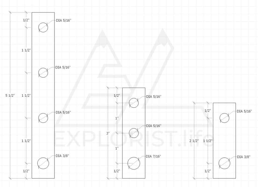
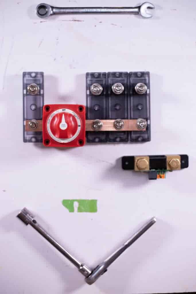
The first thing I’m going to do is to cut and drill my copper bar. Here is a cut and drill list of the pieces I’ll be making. The below diagram has been tested for 2/0 wire equivalent copper bar and switch. If using 4/0 wire, please pre-measure to verify hole placement.
I’m using a Dewalt Portable Band Saw and SWAG Table, but since copper is a soft metal; this could also be cut with a hacksaw.

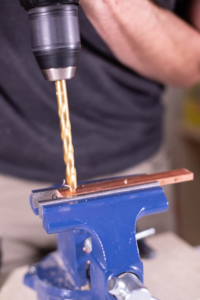
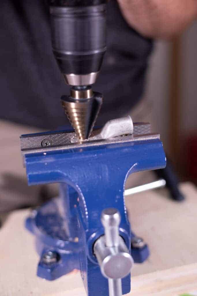
The next thing I am going to do is to clamp those pieces of copper into my bench vise and drill some holes in the copper.
For this I’ll be using a 7/16” Drill Bit, a ⅜” Drill Bit, and a 5/16” Drill Bit spun by a Dewalt Cordless Drill. If I had a drill press or even a high speed corded drill, that would be much preferred… but here we are. Anyway, copper is a soft enough metal so with a fresh, sharp drill bit; this process is fairly painless.
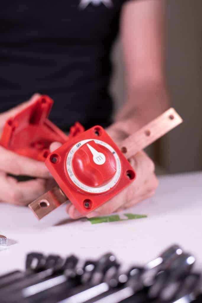
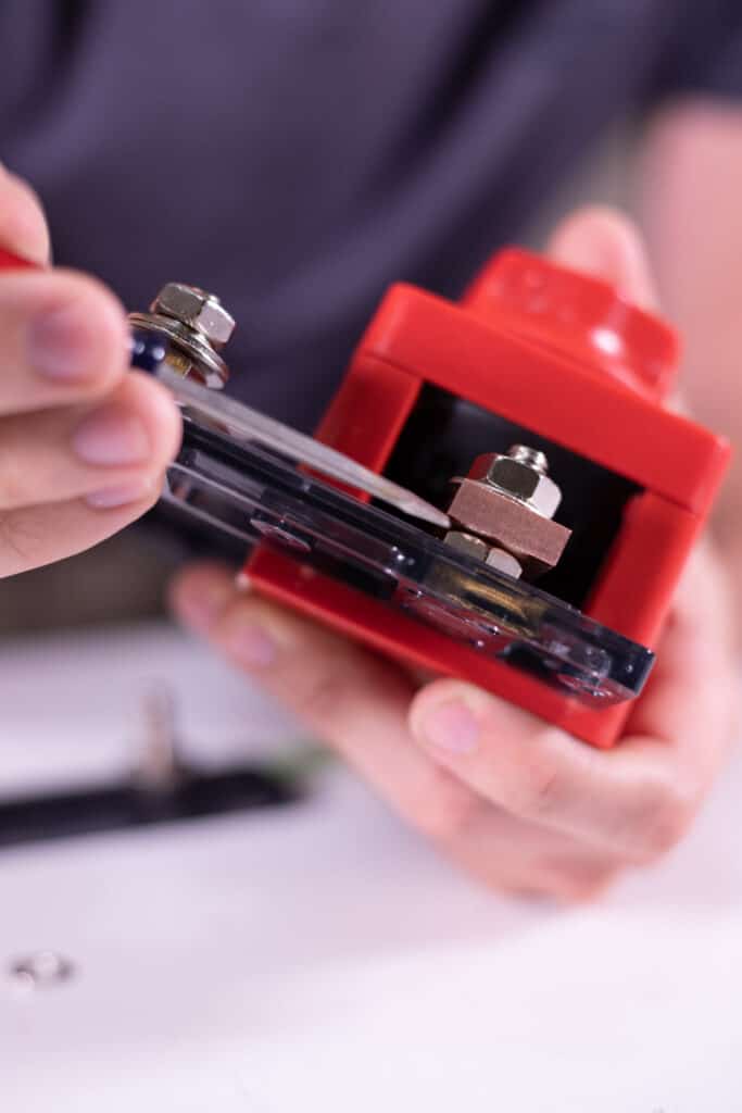
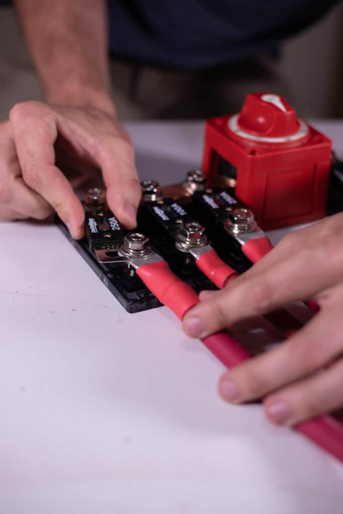
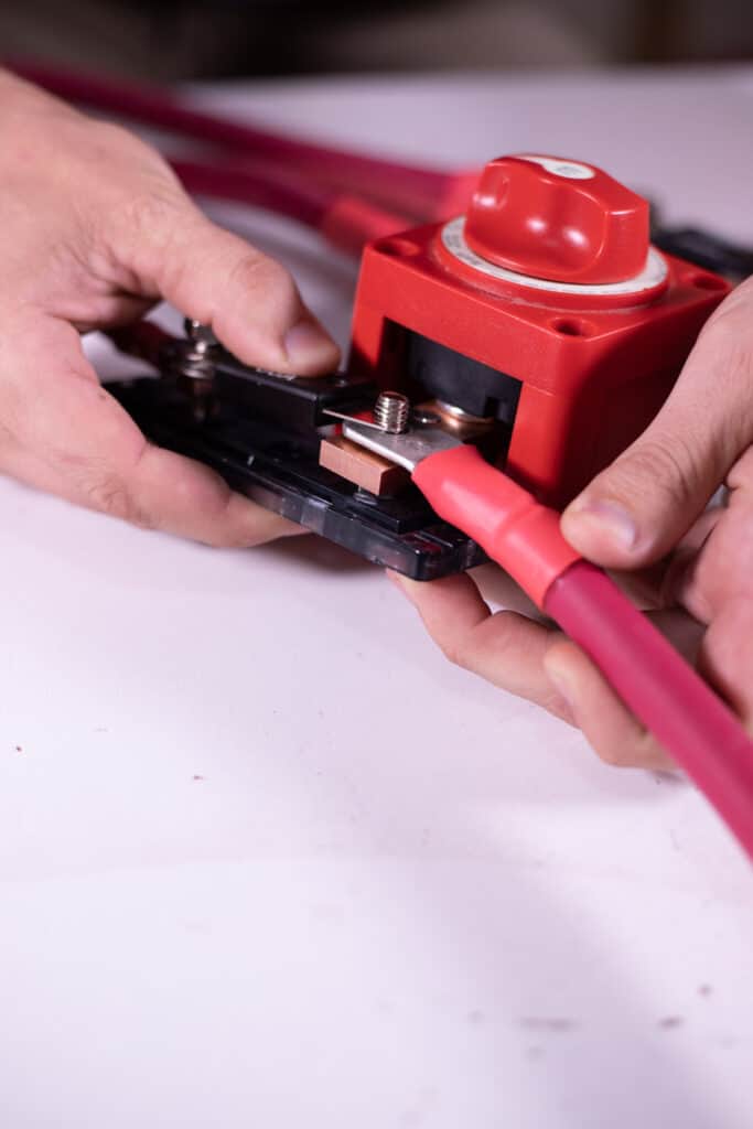
Now I’m going to connect my 2-hole and 4-hole bus bars to my master disconnect switch using a 9/16” Wrench.
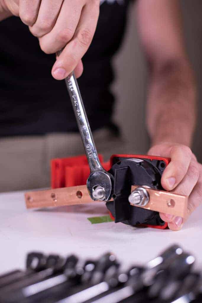
I’m going to position these two busbars so that when I’m looking at the face of the switch; the 2-hole busbar is on the left and the 4-hole busbar is on the right.
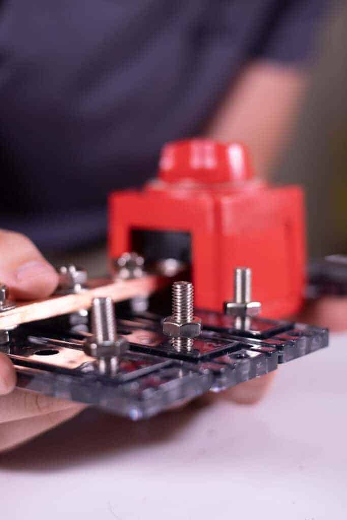
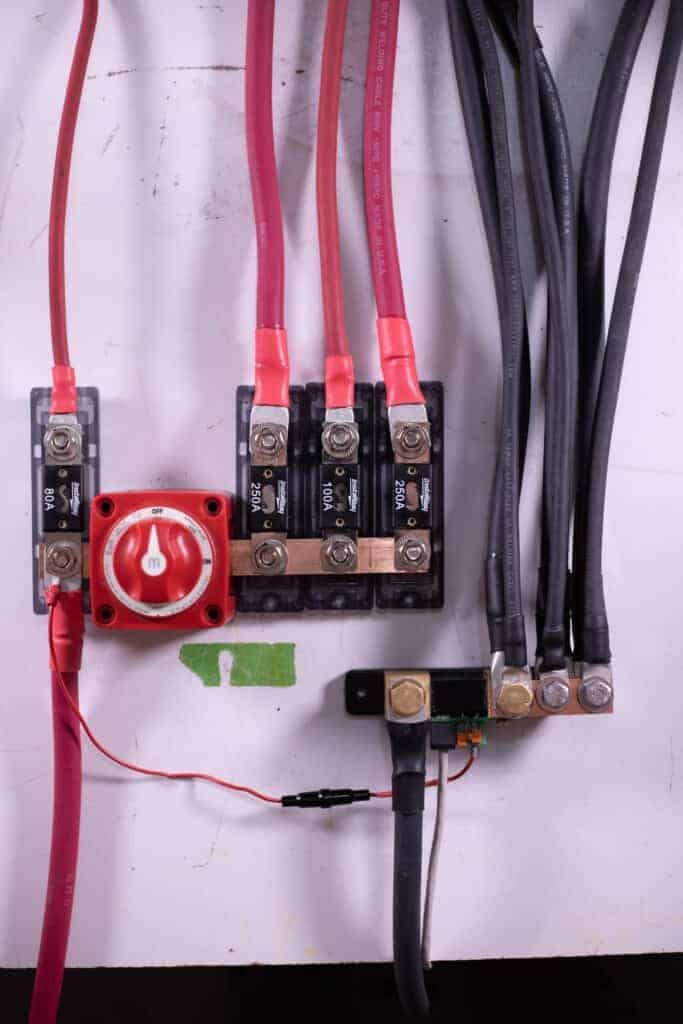
Next, I’m going to install the ANL Fuse holders onto the 3 holes coming off the load side of the master disconnect switch
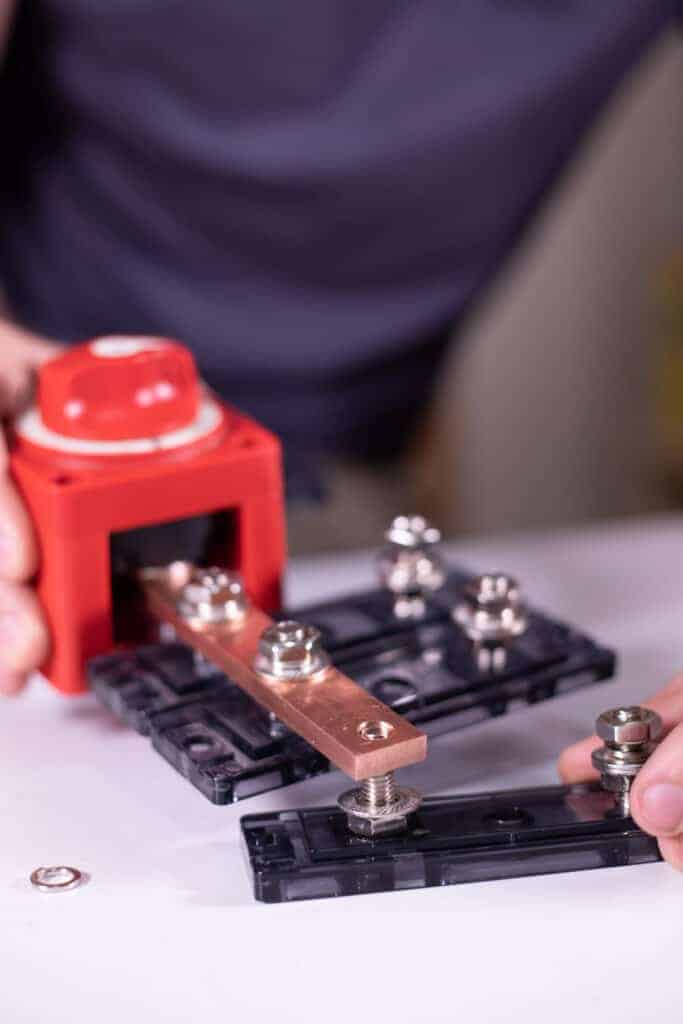
After that, I’m going to do the same thing on the 2-hole busbar side of the master disconnect switch but the one difference will be that I am not going to have the washer below the busbar nor the lock washer above the busbar as there will not be enough room once the wire lug and ANL Fuse is installed.
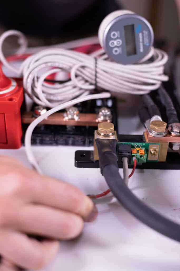
Now would be a good time to fasten my Positive Busbar and the shunt from my Victron BMV-712 Battery monitor in the location that it is going to live within the system. I would position the shunt and positive busbar like this with the “Battery” side of the shunt directly under the right-most ANL Fuse holder:
After those are secure; on the side of the ANL Fuse holders that are opposite the positive busbar I’m going to remove the top nut, lock washer, washers and loosen the bottom nut with a 9/16” wrench and spin it up off the base of the ANL fuse holders about a quarter inch.
Now It’s time to position all of the wires and attach them to the positive and negative busbars using a ⅜” rachet, 6” extension, 9/16” socket, and an 11/16” Socket. All of the positive wires will fit on the ANL Fuse holder studs with a 5/16” lug. Slide the wire lug over the ANL Fuse holder stud; replace the washer and lock washer.

Next I’m going to Install the ANL Fuses. The fuses simply slide in place between the washers like this:
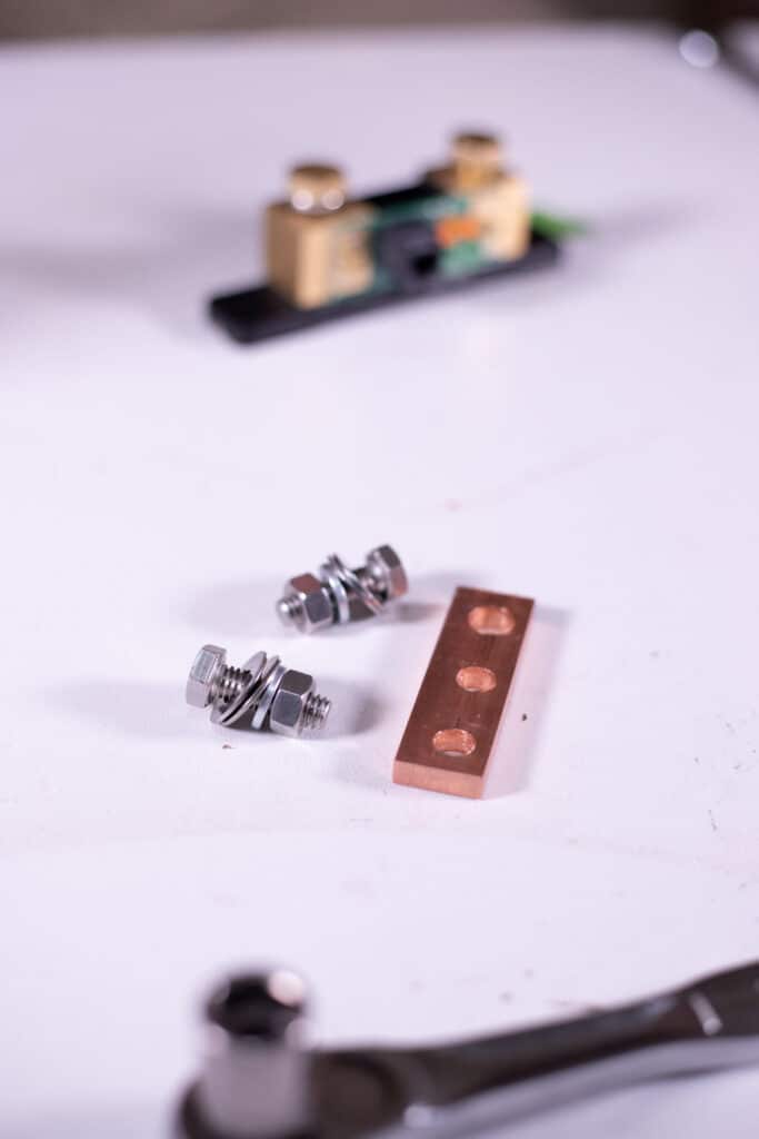
Now I’m going to need the 3-hole busbar, two – 1” long – 5/16’ x 18 hex bolt, 4 washers, and 2 lock washers.
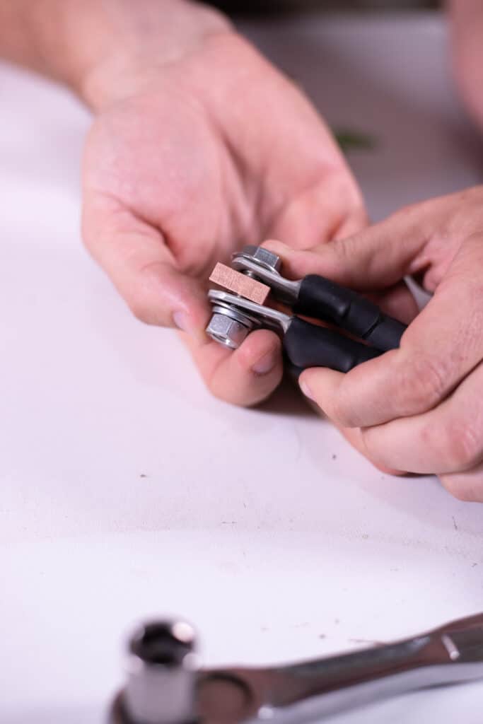
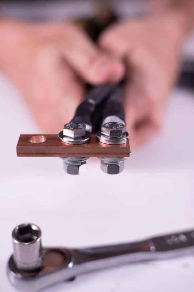
Using the wiring diagram from explorist.life/solarwiringdiagrams as a reference, I’m going to attach the wires with the 5/16” lugs to the 3-hole busbar using the hex bolt setup I just mentioned tightening it up with a 1/2” socket and wrench. I need to position the copper bar itself between the two lugs.
For the remaining two wires on the far left side; these two lugs need to be drilled out with a step bit to fit the bigger bolt of the shunt.
After those lug holes have been enlarged, I’m going to bolt those two lugs and the copper bar to the “Load and Charger” side of the shunt with a 11/16” socket. I don’t have enough room for the washer and lock washer for the shunt so I’m just going to leave them out. Flipping the bottom lug ‘upside down’ will make these two lugs fit together better.
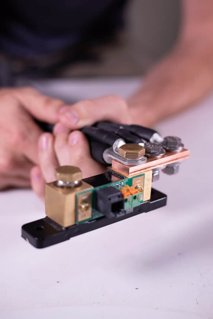
Now, I’ve got a complete positive and negative busbar. The only other thing to do now will be to connect them both to battery power.
I’ll have to enlarge the negative lug with a step bit to properly fit just the same as earlier and attach this lug to this stud with an 11/16” socket.
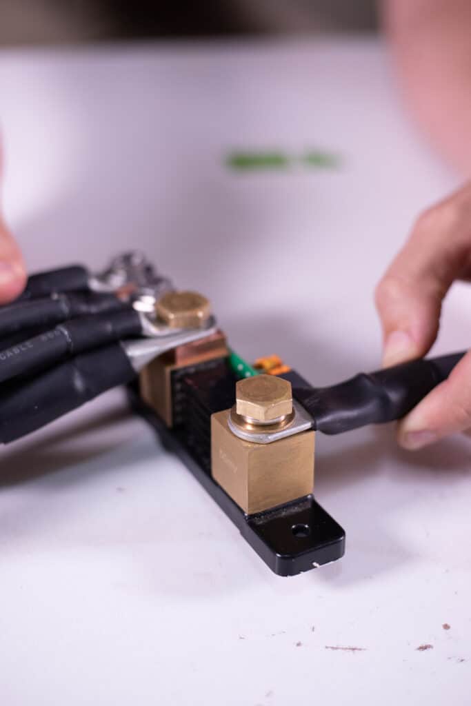
For the positive wire; I need to make sure that the positive lug is directly contacting the copper bar with the fuse sitting on top of the lug rather than below it.
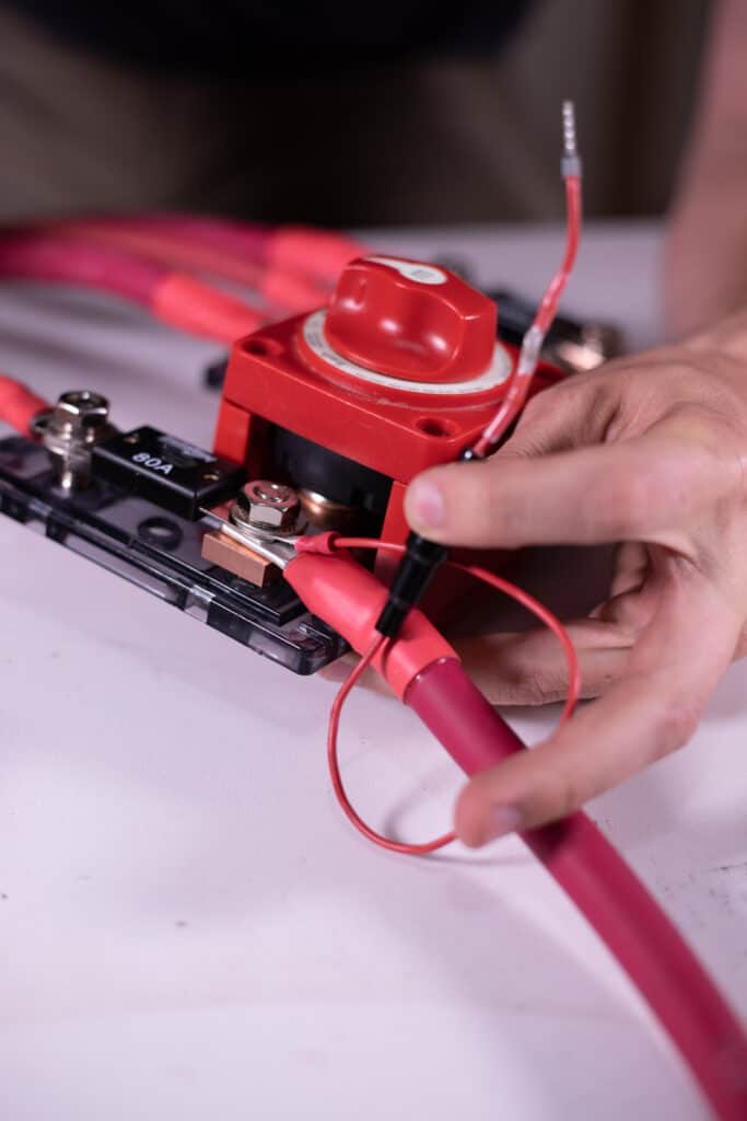
but before I bolt the positive battery cable down, I want to attach the power wire for the little circuit board for the Victron BMV-712.
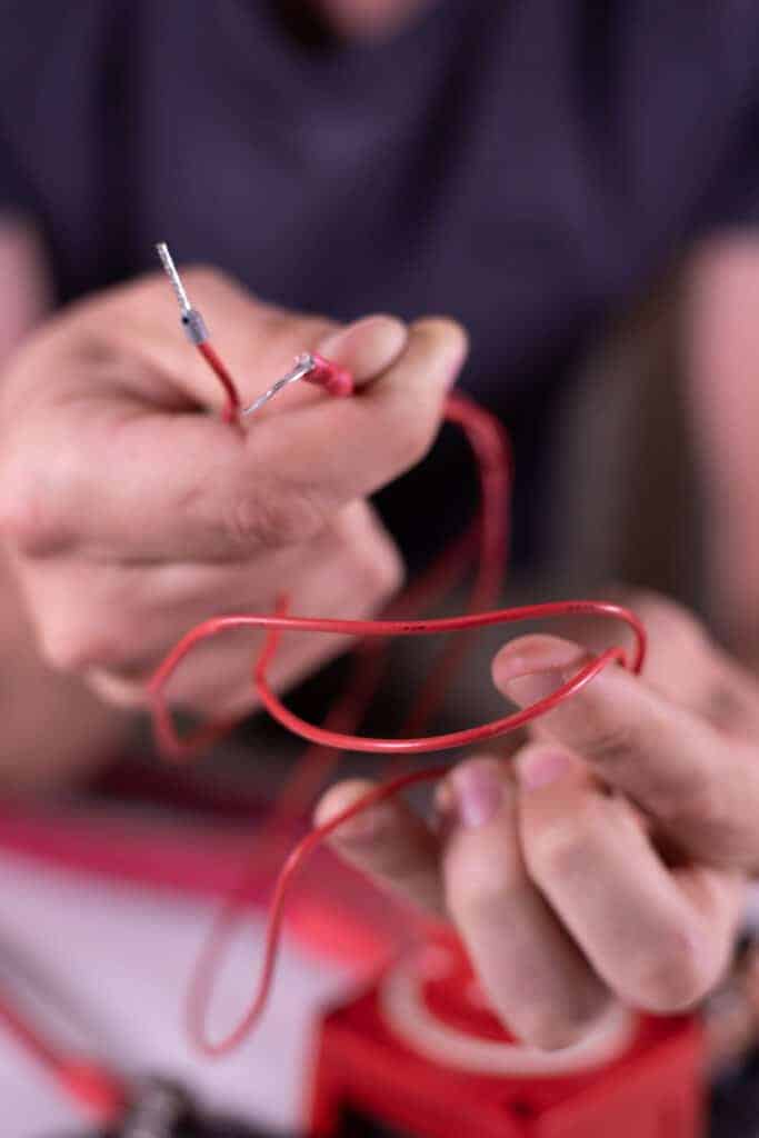
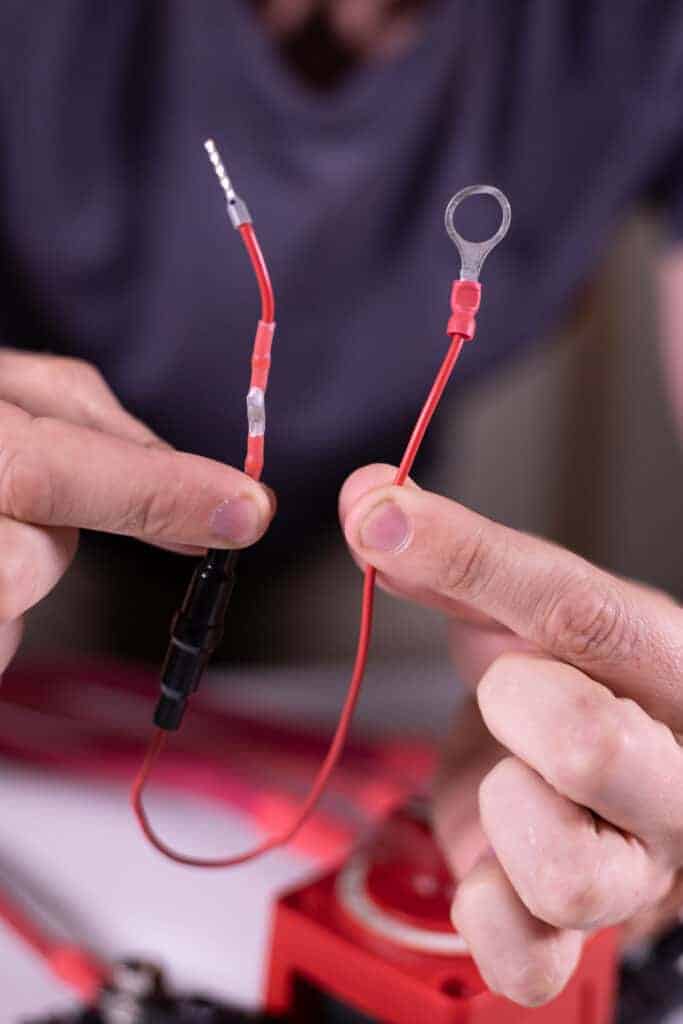
The positive wire for the shunt is really long and I really only need it to be about 14”, so I’m going to cut it down to size and use a butt-splice connector to rid myself of the excess wire making sure to leave the inline fuse intact.
Connect the shunt positive to this stud:
…and connect the other end to the B1 side on the front of the shunt.
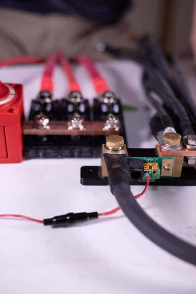
When I get ready to run the Victron BMV-712 Battery Monitor display panel, that data cable simply inserts right here:
And that’s all there is to it!

68 Responses
Hi Nate, Is it ok to connect the end of the positive cable of the solar charge controller to the busbar instead of the end of the positive battery cable? … And then attach the positive cable of the battery to the other end of the ANL fuse?
Yes, but more specifically… I recommend wiring to a Lynx Distributor so the wire has a fuse. Like this: https://www.explorist.life/how-to-wire-a-solar-charge-controller-for-a-diy-camper-electrical-system/
Looking for how people are covering these busbars? Still not wanting to release the STL file for a 3d print?
I no longer recommend making this busbar. I now recommend usinng the Victron Lynx Distributor. It has a cover included: https://battlebornbatteries.com/product/victron-lynx-distributor/?afmc=explorist_bb67
How large of a bus bar do I need if it’s for negative cables only? Or does it not matter? If it does, how do I determine that? Thank you for your time!
The negative busbar needs to be rated for the full ampacity of all of the loads in the system; just the same as a positive busbar.
Okay, thank you! How do I size the system then?
If you haven’t already sized the system… perhaps just use the Lynx Distributor as shown in either of the following two diagrams:
https://www.explorist.life/3000w-inverter-400-600ah-400-to-1200w-solar-camper-solar-kit
https://www.explorist.life/2000w-inverter-200-400ah-lithium-200-to-700w-solar-camper-wiring-diagram/
Okay, good to know, but I would still like to know how to size the system so I know how many amps would be running through the negative bus bar. Thanks!
Hi Nate, you’re a wealth of info!
Regarding the bus bar diagram, I assume the charge controller has a disconnect switch somewhere, correct? Could one locate the charge controller circuit to the side controlled by the main on/off switch…or is it better to separate that circuit?
Thnx again! Rich
It doesn’t REALLY matter if that circuit is separated or not. Like, in my newest systems that use the Victron Lynx Distributor instead of this busbar setup; everything is on the same side of the switch. Example: https://www.explorist.life/3000w-inverter-400-600ah-400-to-1200w-solar-camper-solar-kit
Hello Nate and Steph! I recently discovered the Victron Linx Distributor DC 1000 via your website. Would this do the same task as described above? I am in the middle of installing a Victron Orion 12/12 30a charger to my BattleBorn 100ah battery. My original plan was to go on the (+) side from the Orion > Circuit Breaker > Bus Bar > Battery. Does Linx Distributor house both the bus bar and the fuse that is necessary for this task? Thanks for your time and effort!
Yes! And I’ve implemented the Lynx distributor into both of my most recent diagrams at https://www.explorist.life/solarwiringdiagrams
https://www.explorist.life/3000w-inverter-400-600ah-400-to-1200w-solar-camper-solar-kit
https://www.explorist.life/2000w-inverter-200-400ah-lithium-200-to-700w-solar-camper-wiring-diagram/
Hello Nate! I saw on your pre-made busbars that you sell you had a 3D printed enclosure. Would you consider sharing the design you used for that? I’d love to put the busbars I make based off this guide in an enclosure! Thank you so much for all the wonderful guides 😀
I’m going to keep that proprietary for the time being. Sorry about that!
Hi Nate! Thanks so much for all your work here and elsewhere! So helpful!
I’m building a system big enough to require 4/0 wiring and bought 1″ x 1/4″ copper bar to make it, by mistake? Will that be OK or should I really get the 1 1/2″ bar? How are you coming up with the appropriate size?
It SHOULD be fine as 1/4″ x 1″ will warm up 90 degrees F once the amperage flowing through it reaches 400 amps. So, if you are using a 3000w inverter, that is 250A @ 12V @ 3000W Copper bar ampacity tables: http://www.watteredge.com/pdf/Ampacity_Tables.pdf
please forgive any bad spelling . i like to say thank you your site is very good, easy to follow and agreat sorce of info.
but i do have one queston about bus (buzz )bars
when you contect battreys(say two ) in pannal my understranding is its best to use one pole from each battrey in a diangnal patten to inshore you dont kill the first, battrey
this helps to make the circit run througt both battreys not just load the first(front) one and second battrey only feeding and balanceing the first battrey
but when you use bus bars or wire lungs would this allow both battreys to =(ly) change and give power to the circit ?
i do understand that you have to keep the battrery wires the same length but as im looking in to buying lifep04 battrey and will be upgrading systrem to manage charging and use of said battrey this bus/buzz bar is playing on my mind i guess i could be over think it as the bms on the battreys will do some, if not all the thinking for me but id like to help them as much as poss. lol
thank you for any words of help you could pass on
darrun uk
You COULD use a busbar to combine the batteries together if you like or just go with diagonal wiring. It doesn’t REALLY matter that much.
Does it matter if your ANL fuses are above or below the terminal connections? Everything fits a bit better if they go below for me.
It does not matter.
Thank you for your excellent Youtube videos and tutorials. I made sure to let Dragonfly know I was ordering parts from them based on your recommendations.
I made the busbar.
QUESTION:
Any concern/risk about the copper oxidizing?
Any concern/risk with the copper being exposed (i.e.: what is your reasoning for not putting the copper within an enclosure). Thank you.
Great! Thanks! 🙂
There is little risk of copper oxidizing unless installed in a salty/humid environment like an ocean going boat. Having the copper enclosed is a great idea and is recommended. You’ll just have to get crafty to make the fuse covers fit. In the busbars I’m 3d printing now, I include a cover; so yes… good idea.
Hi Nate, amazing job! Tnx
I’m sizing my 660Wp system with a 24Vdc level at the battery side (250Ah-24V) . Since I have a lower current and also my inverter it’s not more than 1500kW (surge 3kW) i think to use a copper bar 1/8” thick (125Amax)..which bolds, lungs size do you recomend?
Last, question. My 500Ah accumulation is due to my consumptions around 1800Wh/day (80W fridge, laptop, lights, random use of a 400W mixer), so at 24V is 75Ah. Since I use conventional batteries I double it (150h) to not go below their 50% discharge level. So with 500h I have 3days of storage. Finally, if you use lithium tech why have you put 500Ah and not half of that? Or have you sized the system for more cloudy days or for bigger consumptions?
Nice! Sounds good. 🙂
Lithium batteries can be drained to, effictively, 0% without much negative effect so the 50% discharge disclaimer is unnecessary.
Hi Nate. Thanks for all of your work and all the information you provide.
So, I built my busbars for 4/0 cable. When I went to attach the ANL fuses I realized that because I used 1.5″ copper bar and centered the holes, the fuses won’t sit flush on the copper. Can I fill that gap with copper washers ? Or do I need to start over with a new piece of and drill the holes closer to the side ?
Ah, ouch. I must recommend re-drilling the holes. I did that same thing the first time I made this busbar with 1.5″ wide bar.
I just noticed at the top of this post that the 4/0 copper bar is 1/4″X1″. If that’s the case, I can just trim 1/4″ off the side which will solve the problem. Is the 4/0 copper bar 1″ or 1.5″ ?
Hi, Nate. So glad for all your great information! I see the MPPT controller happens to be one side of the positive busbar, but everything else is on the other side of the master disconnect. When the master disconnect is turned off, will the MPPT controller also turn off? In other words, will EVERYTHING on the positive busbar be turned off when the master disconnect gets turned off? Thanks!
Hey Azhiker,
I saw Nate respond to the same comment on the YouTube video.
“Doing it like this makes it nice and easy to disconnect all loads while allowing the solar panels to keep the batteries topped off. If the solar controller needs to be turned off you can do that through the VictronConnect app or by pulling the fuse but there is rarely a reason to disconnect the charge controller.”
– From Nate
Thanks for picking up my slack Jason. 🙂 Cheers!
Hi, Nate.
I don’t see a link to the negative shunt. Can you supply that?
Thanks!
The shunt is included in with the Victron BMV-712 listed in the parts list at the top of the page.
I’m really grateful for your tutorials! A couple questions, due to the size of my system, I have two charge controllers. Would I make two Busbar holes, then connect a negative and positive from each end of the battery bank to both charge controllers on the Busbar?
Also, I’m not interested in including the Victron BMV-712 in my setup. If I omit the shunt on the negative Busbar, is the battery cable simply placed next to the others?
Yes, an additional hole in the negative busbar would be needed and an additional fuse on the positive busbar would be needed.
If no battery monitor is to be used, the wire from the battery could, indeed, be connected directly to the negative busbar; omitting the shunt.
I would strongly consider some kind of shunt based battery monitor of some kind. Getting rid of this would be like getting rid of the fuel gauge and speedometer in your vehicle.
Hi, Nate! These diagrams and videos have been a LIFE SAVER! I’m following them pretty closely in my design, but with a few slight changes – I am not using the Victron Battery Monitor, which means I will not have a shunt to use on my DIY Busbar. What do I need to change because of this?
I suppose you could just mount the copper bar onto a ‘junction stud’ but I would plan your space to eventually add a shunt because not using a shunt is like driving a car without a fuel gauge and I think you’ll regret the decision eventually so I’d definitely recommend accounting for the space to add one eventually.
I understand that it would protect the battery bank but doesn’t it also mean you really can’t use an inverter and 12V accessories at the same time with this setup?
I would also like to know the answer to this question.
12v and 120v devices can absolutely be used simultaneously with this setup.
I see 600 amps worth of fused wire feeding a switch that’s only rated for 300 amps…
What happens when these wires send more than 300 amps through the switch?
In that case the terminal fuse mounted on the battery bank would blow. The terminal fuse on the battery bank is protecting the wire from the battery to the busbar, the busbar, and the switch.
Hey Nate,
We built our own box to house all of these electrical components, however I am unsure how to safely mount the negative busbar…should I put a rubber mat between the wooden box and the copper it will be mounted to or are you just using the shunt to mount the bar and letting the copper hang? Trying to do this the safest way…
Just using the shunt to support the busbar. With all of the cables attached and secured with zip ties everything locks down very well.
Correct if im wrong but the photo on the very bottom seems to have the shunt power cable in B2 not B1 as a few photos above. ( power for the victron) can you please clarify ? Thanks.
It should be in B1.
Super helpful – thanks for all your content.
Just looking through the diagrams – would I benefit in swapping the smart relay for a battery to battery charger. My vehicle doesn’t have a smart alternator, but am told the B2B are essential when using LiFEPo batteries.
I very much like the battery to battery chargers. I’ve incorporated one into my newest diagram: https://www.explorist.life/3000w-inverter-400-600ah-400-to-1200w-solar-camper-solar-kit/
Hey guys!! Putting together a setup and your channel/info has been a staple part of the planning, so thank you so much!
Just wondering how you prevent/minimise the risk of short circuiting with having the whole bus bar ‘live’ and so exposed?
Might be a dumb question but I’m a novice so forgive me 😉
You could always find a way to enclose it into a box or get crafty with notching out the ANL Fuse Holders.
I love your solar diagrams. Such a clean implementation of an electrical system.
Question for you… How do you have the bus bar mounted in your van? Do you encase it a box of some sort? I have two children and even though it’ll be in an electrical compartment I don’t want anybody to accidentally touch it. Do you have any recommendations on how to encase it?
I don’t have any specific recommendations for how to inclose it, but there are a ton of ‘project box’es on amazon you could get crafty with to find a solution to that issue.
Okay, so I’m a super beginner in this world haha. I’m looking at a bunch of different designs to try and understand everything before I get started on my own system. I’ve been LOVING your articles, between you and “faroutride” I think I’m going to be able to pull this off haha. I was, however, wondering why you decided to go with all the individual fuses? Would I be able to replace all of those small fuses with a fuse box instead? Thanks!
Glad you’ve found it helpful! You can’t use small ‘spade fuses’ in a fuse box for this application as we may potentially be asking this to be able to handle well over 200 amps when we kick on our inverter or charge from our alternator. Most fuse blocks are only good up to a MAX of 100 amps.
How did his butt splice connections work? I assume a heat gun does not get hot enough to melt the solder. Thanks!
Actually, it does. 🙂
Im retired now but I was an electrician for 44 years. Your work is excellent sir.
Thanks! 😀
Great set of instructions. Do they not sell lugs that have a 7/16 opening?
Not sure. I typically just buy 5/16 in bulk and drill them out as necessary.
Is it possible to charge when on shore via the on shore supply?
Of course! All of the wiring diagrams that use this busbar system are capable of charging via shore power. See here: https://www.explorist.life/solarwiringdiagrams
I like this method! What size copper bar stock is that?
Thanks! It’s a pretty elegant solution for sure. 1/4″ x 3/4″ copper bar is the 2/0 wire equivalent.
Great Work Nate!
I am a little confused when you would use the on/off switch on the Bus. What position when on shore power?
Thanks,
Bill
Thanks! That master disconnect would be for if you plan on not using the system for a while (say, in storage) or for maintenance in the system. Under normal operation; that switch would remain in the on position.
In the wiring diagram for the 600w/400aH set up, are the 120v breakers just mounted on a bar or are they inside a “breaker box”, or both?
Stand-by on that one. I’m going to make a new video blog post about that within a few weeks.