
This blog post will teach you how to wire a solar charge controller in your DIY camper electrical system. A solar charge controller regulates the power coming in from the solar array and converts it to a voltage and amperage that is safe to charge a battery bank with.
Parts & Tools Necessary to Wire a Solar Charge Controller
| Column A | Column B | Column C | ||
|---|---|---|---|---|
| This parts list shows all of the parts used in this tutorial. Your wire, fuse, and ferrule sizes will vary depending on the charge controller you are using for your array. | ||||
| Product | Qty | Link | ||
| Victron Smartsolar Charge Controller | 1 | |||
| Lynx Distributor | 1 | |||
| 10 AWG Red Wire | 5 | |||
| 10 AWG Black Wire | 5 | |||
| 6 AWG Red Wire | 5 | |||
| 6 AWG Black Wire | 5 | |||
| 6 AWG x 5/16" Wire Lug | 3 | |||
| 6 AWG x 1/4" Wire Lug | 1 | |||
| 6 AWG Ferrule | 2 | |||
| 10 AWG Ferrule | 2 | |||
| 60A MEGA Fuse | 1 | |||
| Cable Clamps | 3 | |||
| 3/4" Truss Head Screws | 3 | |||
| Wire Duct | 1 | |||
| 1/4" Red Heat Shrink | 1 | |||
| 1/4" Black Heat Shrink | 1 | |||
| 1/2" Red Heat Shrink | 2 | |||
| 1/2" Black Heat Shrink | 4 | |||
| #14 x 3/4" Pan Head Screw | 4 | |||
| Junction Stud | 1 | |||
| These are the tools that were used in this project. | ||||
| Wire Crimper | 10 AWG - 4/0 | 1 | |||
| 8" Diagonal Cutters | 1 | |||
| Wire Strippers | 12 AWG - 6 AWG | 1 | |||
| Adjustable Wire Strippers | 1 | |||
| Impact Driver | 1 | |||
| Multimeter | 1 | |||
| Phillips Head Screwdriver | 1 | |||
| Flat Head Screwdriver | 1 | |||
| 13MM Socket | 1 | |||
| 3/8" Rachet Extension | 1 | |||
| 3/8" Rachet | 1 | |||
| Heat Gun | 1 | |||
| Ferrule Crimper | 10 AWG - 6 AWG | 1 | |||
Turn off all Power in your System
Verify that you have no power flowing in your system. This means that you need to:
- Turn off your main battery disconnect switch
- Unhook from shore power
- Turn off all components (like your Inverter)
- Turn off your Solar Disconnect Switch
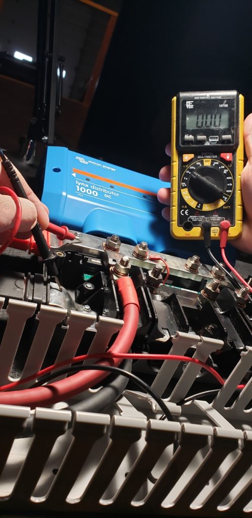
Using a multimeter to check for zero voltage at your positive and negative busbars and at the wires coming from the solar charge controller is a good idea at this point.
Wire the Solar Charge Controller Equipment Ground
The equipment ground screw needs a clear path back to the negative busbar in the Victron Lynx Distributor. This is important for if there is a catastrophic malfunction inside of the Lynx Distributor, there is a path back to the negative busbar so that power can flow in order to complete the circuit which would allow the fuse protecting the circuit to blow.
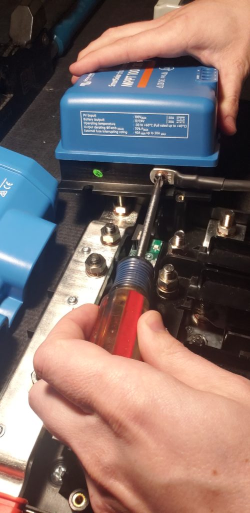
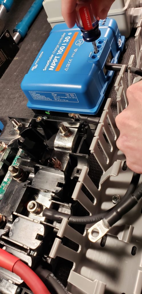
This is the solar charge controller equipment ground screw:
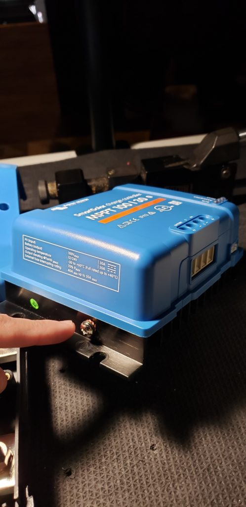
You need a wire with a 1/4″ wire lug on one side and a 5/16″ wire lug on the other side to make this connection
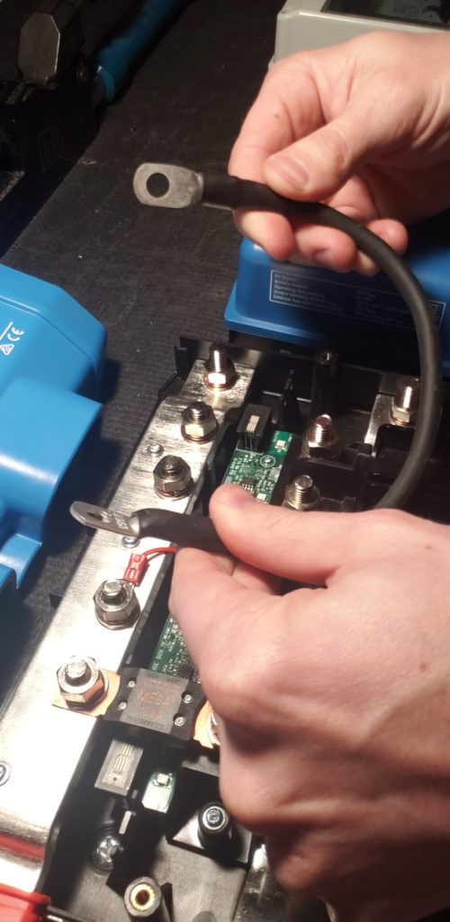
- Remove the Screw and washers using a phillips head screwdriver
- Place the 1/4″ wire lug against the heat sink
- Replace the washers and screw.
- Tighten to an appropriate torque.
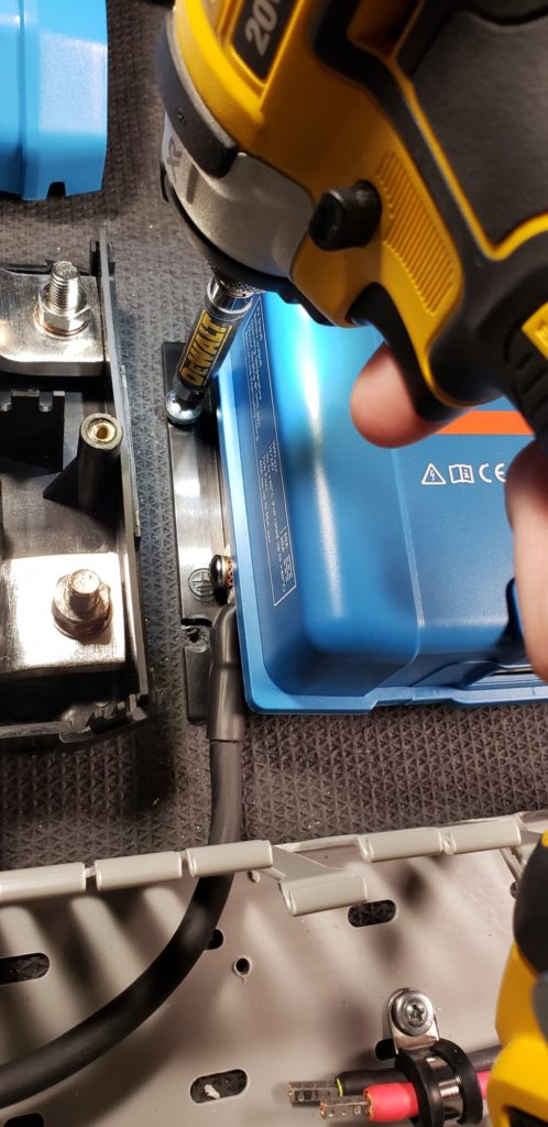
Screw the Solar Charge Controller to the Backer Board
Since the ground screw is in an awkward place on the side of the charge controller and makes it difficult to access once there is a component to the left of the charge controller, it’s important to make that connection first. Now you can screw the charge controller to the backer board. 4x #14 x 3/4″ Pan Head Screws work great for this charge controller.
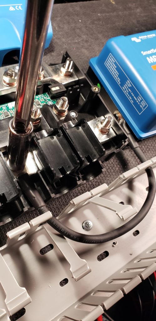
Attach the Equipment Ground Wire to the Negative Busbar
The next step is to attach the solar charge controller equipment ground wire to the negative busbar. This will go to the center stud on the negative busbar inside of the lynx Distributor.
- Remove the nut, washer, and lock washer with a 13mm socket.
- Place the 5/16″ wire lug onto the stud
- Replace nut, washer, and lock washer with a 13mm socket.
- Tighten to an appropriate torque
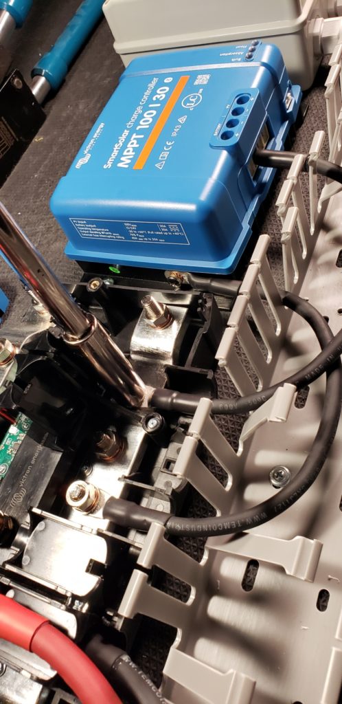
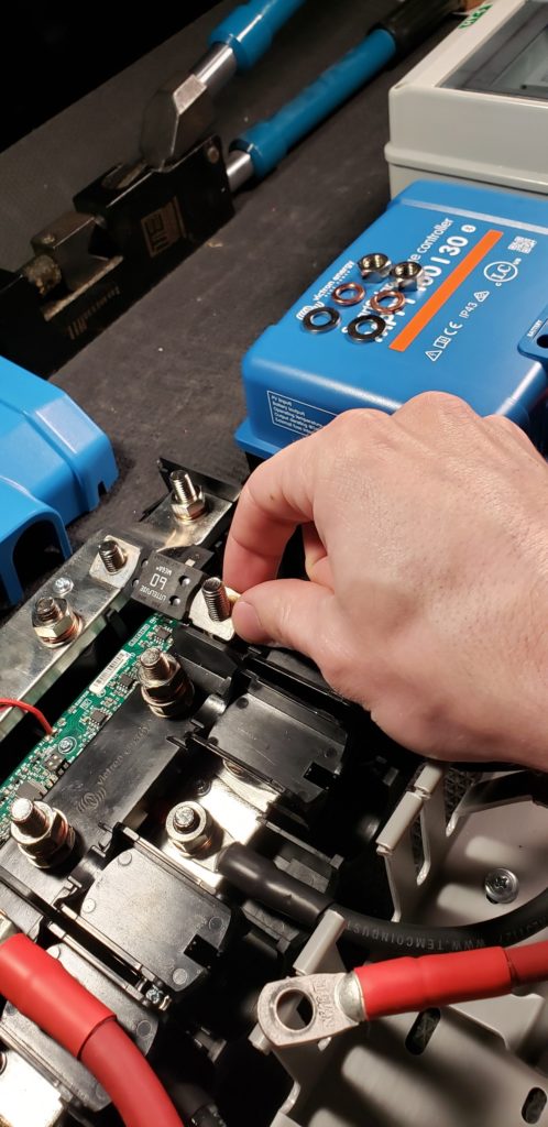
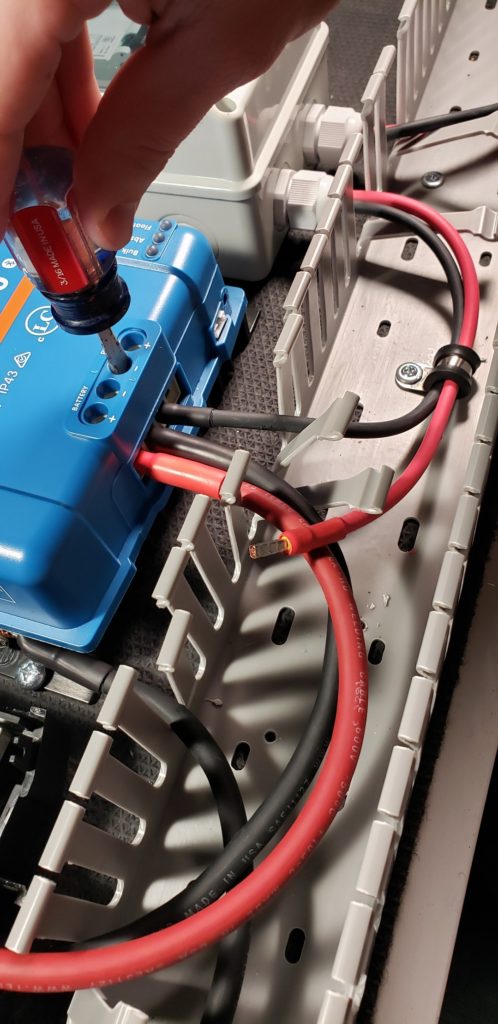
Wire the Solar Charge Controller Battery Negative Wire
Now I am going to wire the solar charge controller from the charge controller battery negative terminal to the negative busbar in the Victron Lynx Distributor.
To make this connection, I’ve made a wire with a 5/16″ wire lug on one side and a ferrule on the other side.
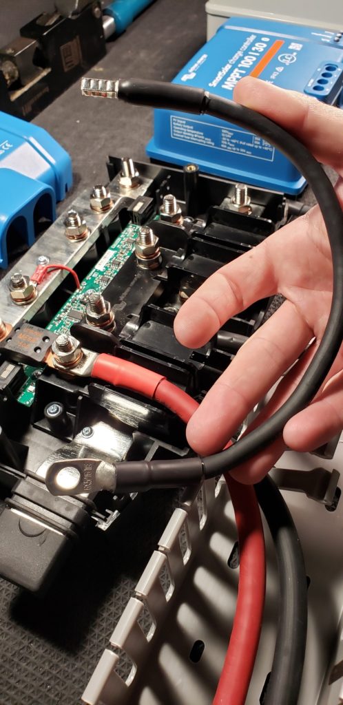
(Note: Ferrules are completely optional throughout this tutorial, but make for a very clean install. A stripped bare copper end of stranded wire is also an approved method.)
Next, I’m going to place the end with the ferrule in to the battery negative terminal of the solar charge controller and tighten the screw.
Now I’m going to connect the end with the 5/16″ wire lug to one of the studs in on the negative busbar inside of the Victron Lynx Distributor:
- Remove the nut, washer, and lock washer with a 13mm socket.
- Place the 5/16″ wire lug onto the stud
- Replace nut, washer, and lock washer with a 13mm socket.
- Tighten to an appropriate torque
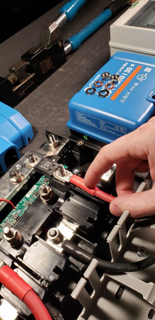
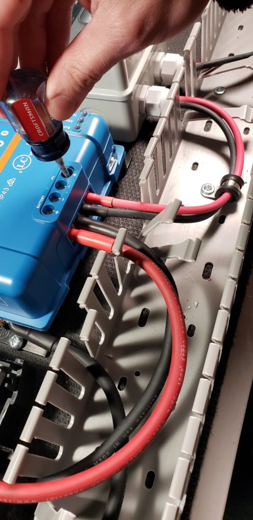
Wire the Solar Charge Controller Battery Positive Wire
Now I am going to wire the solar charge controller from the charge controller battery positive terminal to the positive busbar in the Victron Lynx Distributor.
To make this connection, I’ve made a wire with a 5/16″ wire lug on one side and a ferrule on the other side.
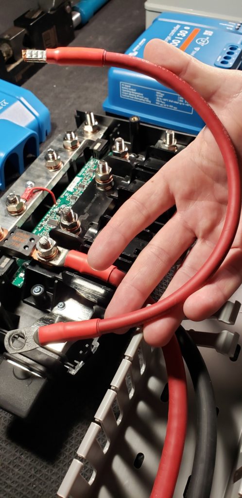
I’m going to place the end with the ferrule into the battery positive terminal of the solar charge controller and tighten the screw.
Now I’m going to connect the end with the 5/16″ wire lug to one of the bottom ‘fuse holder’ studs and use a MEGA fuse to connect the wire lug to the positive
- Remove the nuts, washers, and lock washers on both of these studs with a 13mm socket.
- Place the MEGA Fuse in place
- Place the 5/16″ wire lug onto the bottom stud
- Replace nuts, washers, and lock washers on both fuse holder studs with a 13mm socket.
- Tighten to an appropriate torque
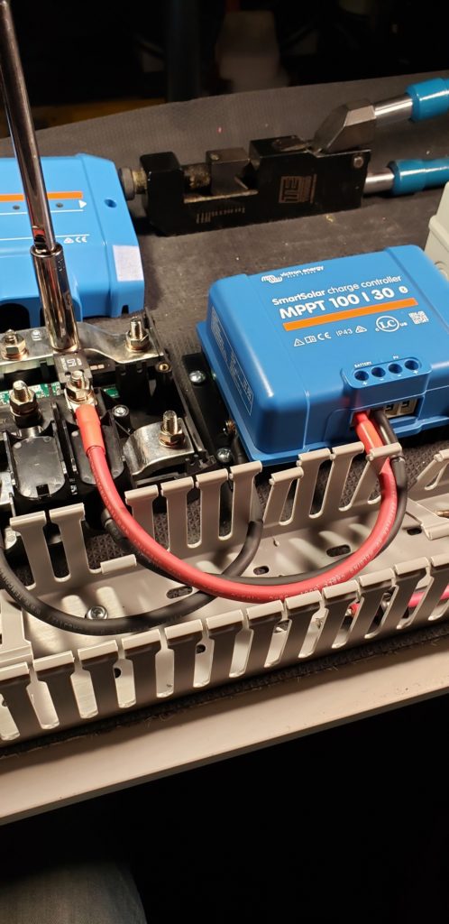
How to Wire a Charge Controller to a Solar Disconnect
Connecting the charge controller to the solar disconnect is simply a matter of connecting a positive and negative wire from the solar disconnect to the charge controller and tightening the terminals screws.
To wire the solar disconnect to the charge controller, I’m going to crimp on some ferrules onto the wires that are coming from the solar disconnect.
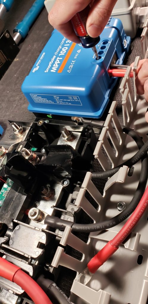
Wire the Solar Charge Controller Solar Negative Wire
Now I’m going connect the negative wire that goes from the solar disconnect to the charge controller:
- Insert the negative wire into the PV negative terminal on the charge controller.
- Tighten the screw down to an appropriate torque.
Wire the Solar Charge Controller Solar Positive Wire
Now I’m going connect the positive wire that goes from the solar disconnect to the charge controller:
- Insert the positive wire into the PV positive terminal on the charge controller.
- Tighten the screw down to an appropriate torque.
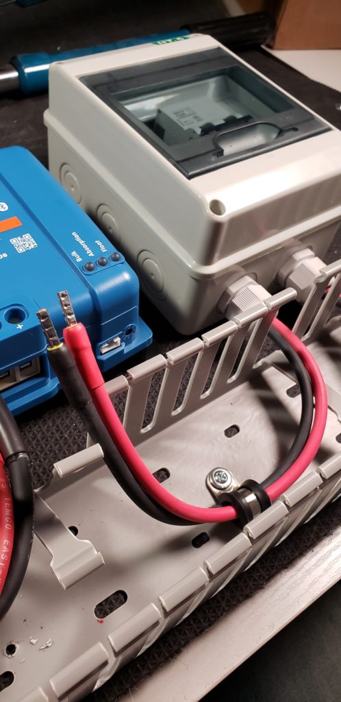
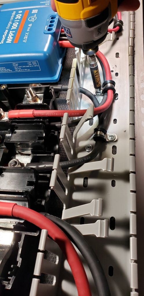
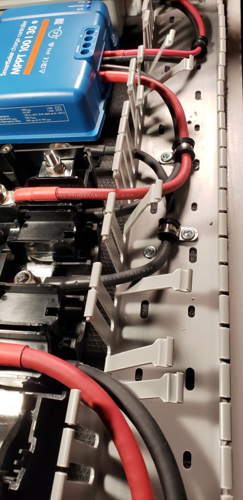
Use Cable Clamps for Wire Management
To keep the wires nice and tidy inside of the wire duct AND to keep the wires from wiggling out of the charge controller terminals, I’m going to put some wire clamps on the wires we just installed inside of the cable duct.
Double-check your Connections for Proper Polarity
Once all of the wires are connected, it’s time to go through and verify that positive wires are connected to positive wire terminals; and negative wires are connected to negative wire terminals. Systematically tracing each wire with your finger and pointing to the positive terminals is a great way to visualize that each wire is where it should go.
Turn on Battery Power to your System
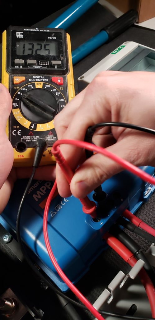
Now I am going to turn on battery power to my system and if all goes well, I should be able to take a voltage reading with my multimeter and see somewhere in the 11-14.6V range for a 12V battery bank registering at the positive and negative battery terminals on my charge controller.
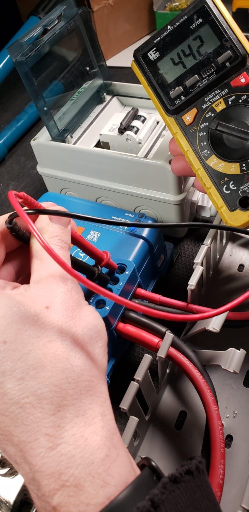
Turn on Solar Power to your System
Next, I can turn on the solar disconnect switch to connect my solar array to my charge controller. If all goes as planned, my solar array voltage should read at my positive and negative PV input terminals on my solar charge controller. Since I have 2x 100W solar panels wired in series, a reading of 44V is expected. Your solar array voltage may vary depending on it’s configuration.
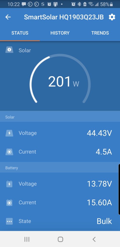
Verify that your Solar Array is Charging the Batteries through your Charge Controller
Lastly, I am going to pull up the VictronConnect app on my phone and see that my batteries are indeed charging my battery bank at a rate of 15.6A
Installing a Solar Charge Controller – Finishing Up
The last steps for this project is to put the covers back on the Victron Lynx Distributor, replace the wire duct cover, and sit back and admire your handiwork on your newly installed solar charge controller.
Thanks for reading and I hope you found this blog post helpful and if you did… It’d be awesome if you would share it with somebody, or a group, who you think could use it. Hit the like button, and leave any questions you’ve got in the comments section below. Subscribe if you want to see more DIY camper building tutorials and I… will see you in the next project.

16 Responses
I’m getting ready to buy an MPPT for my solar panels. First, I’m confused why anyone would want an MPPT that handles over 30A since you say in several videos that MC4 connectors generally cannot handle over 30 A? In my case, I have four 50W panels (18.6V,2.7A) and I’m planning to put another four 175 W panels (18V,9.7A) in a 4s2p arrangement which means 72V,12.4A so I’m looking at a Victron MPPT 75|15. I always like to have room for future changes, but a MPPT 100|30 for double the cost doesn’t make sense if I can just connect a second MPPT 75|15. Or am I missing something?
You’re confusing input amps vs output amps. This video should help: https://www.youtube.com/watch?v=Jkbs84sBHsg&list=PLmvhcyi4n0TV9pi83rFTv3ZuMT_S1xIZt
@Nate Yarbrough, You are exactly right. Thanks! But I still wonder about solar arrays > 30A.What should people do then? Throw out the MC4’s and substitute crimp connections? Solder? Thanks again.
I recommend never never never designing a solar array over 30A. There is truly no need. The big SmartSolar MPPT 250|100 has a max wattage of 5800W and I could max that thing out without exceeding 30A on the array.
Any thoughts on wiring a solar charge controller for charging a nominal 48v battery? I find your diagrams wonderful, but there are a few quirks when working with 48v, seems to me.
I have questions about both wire sizing and fuse selection. I have Victron 150/35 controllers (2 of them) and a Lynx Power In. Your groovy wiring calculator suggests 12AWG and the Victron manual suggests a 40 Amp fuse (which matches up with the wiring size) and says “45amp maximum”. See 4.2 here: https://www.victronenergy.com/media/pg/Manual_SmartSolar_MPPT_150-35__150-45/en/installation.html I’m not really sure why there is a maximum fuse specified.
Thing is that Victron only make Mega fuses for 48v nominal (58v for 48v systems) down to 125Amps. They do make 58v MIDI fuses down to 30amp (including a 40amp fuse).
So would you:
1. Size the wire up to make a 125amp MEGA fuse work? or
2. Use a MIDI fuse holder outside the Lynx? e.g., CIP000050001
3. Use some copper bar to “extend” the MIDI fuse to fit inside the Lynx? That’s described here: https://diysolarforum.com/threads/fitted-a-midi-fuse-in-a-victron-lynx-distributor-is-it-ok.22397/#post-401352
I have two other 48v loads, a Victron Orion 48-12 (30amp at 12v) and a 48v HVAC system (30amp max at 48v). So I have a mild preference to avoid the external MIDI fuse holders for space (also means extra connections).
Thanks,
James
I would size the wire up for that. For all of the 150|xx and 250|xx charge controllers, I always just use 2 AWG as a blanket statement from the MPPT to Lynx Distributor as it’s the biggest size that fits. If you do that, you can use the smallest MEGA fuse you can find (60A usually).
All your diagrams show the solar charge controller wired on the distributor which is connected to the battery via the isolation switch. This would mean that if you isolate the battery, it would kill power to the controller. Everything I read says that you should not do this while the panels are connected, so would you then have to trip the breaker to isolate the panels first.
This means that you cannot be charging the battery while it is isolated from the DC loads, or would you have a second switch for this?
The solar would not be charging the battery with the DC loads isolated. If you want to charge via solar, just keep the main battery disconnect on and turn off all of the loads at the device.
Thanks for all this! I have a question on sizing the DIN rail boxes for the solar disconnects. The HT-5 box linked to from the parts list says that it is “5 ways” and I think you fit two of the double pole breakers in there in your “How to install two Solar Charge Controllers” video (https://www.youtube.com/watch?v=N0UB7LZVduk) (ie 2 x 2P), is that right?
I see other DIN rail boxes listed as “8-way”. Does that mean they can take up to 4 of these double pole disconnects?
Yep! Exactly.
I have purchased the electrical diagram from your site. The diagram indicates that a 2 awg wire needs to go from the charge controller to the distribution panel. However, the 2 awg is a huge wire (as you well know) and even when I tried to install a ferrule on it, it will not fit the small hole of my charge controller. How exactly do I overcome that?
Thanks!
Monica
If 2 AWG is too big, that leads me to believe that you are using either a Smartsolar MPPT 100/30 or 100/50. Both of which have a max wire terminal size of 6 AWG. This change is noted in the “Solar Charging Parts List & Wiring Diagrams” section near the bottom of the parts list / blog post for whatever diagram you are looking at.
Nate, I purchased the 3000w wiring diagram and it doesn’t specify the gauge of the ground wire to the MPPT. I was hoping to see it listed here but I still don’t see anything. Any help would be appreciated.
Thanks…
Jay
The ground wire is the same size as the wires going from the charge controller to the Lynx Distributor. So, 2 AWG for 150 & 250V charge controllers or 6 AWG for 100V charge controllers.
Hey Nate, Samantha again!
I was wondering if this charge controller needs to be purchased for the 3000w DIY Solar setup that you showed? I am following that diagram for my setup, but I don’t see in the shopping/parts list a product link for the Victron MPPT 250|100 -Tr Charge Controller which shows in the wiring diagram..? I purchased 2 100w 12v mono Renogy solar panels so far and plan to get up to 500-800w eventually, but I just realized I have yet to purchase a charge controller which is right under another $1k! Was that just forgotten on the product list or am I missing something here? I have been researching so much and I can get a bit overwhelmed with this stuff. Thank you!
Be sure to check the ‘Solar Parts List’ dropdowns at the bottom of the blog post to see what needs to be added for various sizes of solar arrays: https://www.explorist.life/3000w-inverter-400-600ah-400-to-1200w-solar-camper-solar-kit/#solar-parts-list