This blog post will teach you what size of wire you need to wire your solar panels to your charge controller in your DIY camper electrical system. We will cover the ‘technical’ way to size wire and the ‘easy’ way to size wire.
The technical way to size solar array wire involves using the EXPLORIST.life wire sizing calculator to determine the proper size of wire based on the amps, voltage, allowable voltage drop, and length of the circuit.
The easy way involves verifying that 10 AWG wire is big enough and simply using 10 AWG Wire for the solar array wiring.
How to Choose Solar Panel Wire Size – Video
This video will teach you what size of wire you need to wire your solar panels to your charge controller in your DIY camper electrical system and will cover all of the concepts from this blog post
Wire Size Calculator
The EXPLORIST.life wire size calculator can always be found at https://www.explorist.life/wire-sizing-calculator/ and can be easily accessed by using the main website menu under the ‘Calculators’ heading. Since it is vital to this blog post, I will also embed it here:
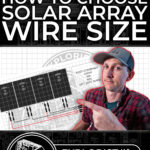
Series Wired Solar Array Wire Size
A series wired solar array gets the voltage of each panel added together while the array amperage remains the same as a single panel.
This means that in the example below, there is 5 amps at 80 volts flowing through the wire from the solar panel to the charge controller.
It is 20ft from the solar array to the charge controller, which means that the 5 amps at 80 volts is flowing through 40ft of wire. Allowing for 3% voltage drop in the wire sizing calculator, we can see that we can use 16 AWG Wire for these wires.
Try it for yourself. The inputs are:
- 5 Amps
- 80 Volts
- 40 Feet
- Wire NOT installed in an engine compartment
- Only 2 wires in the bundle
- 3% allowable voltage drop
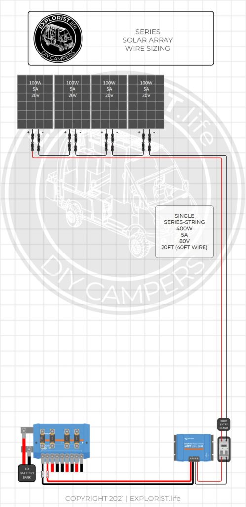
Parallel Wired Solar Array Wire Size
To determine the wire size necessary for a parallel wired solar array, we need two separate wire size calculations. Since the voltage and amperage flowing through the wires before the combiner is different than the voltage and amperage flowing through the wires after the combiner, we need to find the recommended wire size of each.
This means that in the example below, there are 5 amps at 20 volts flowing through the 20ft of wires from each of the solar panels, 10ft away to the MC4 Combiner. Allowing for a 1.5% voltage drop in the wire sizing calculator, we can see that we can use 14 AWG Wire for these wires.
After the Combiner, since parallel wired panels get their amperages added while their voltages stay the same, the wires would be delivering 20 amps at 20 volts through 20 feet of wire, 10 feet away to the charge controller. Allowing for a 1.5% voltage drop in the wire sizing calculator, we can see that we can use 8 AWG Wire for these wires.
Try it for yourself. Here are the inputs used:
- For Each Panel to the MC4 Combiner
- 5 Amps
- 20 Volts
- 20 Feet of Wire
- 1.5% allowable voltage drop
- From the MC4 combiner to the Charge Controller
- 20 Amps
- 20 Volts
- 20 Feet of Wire
- 1.5% allowable voltage drop
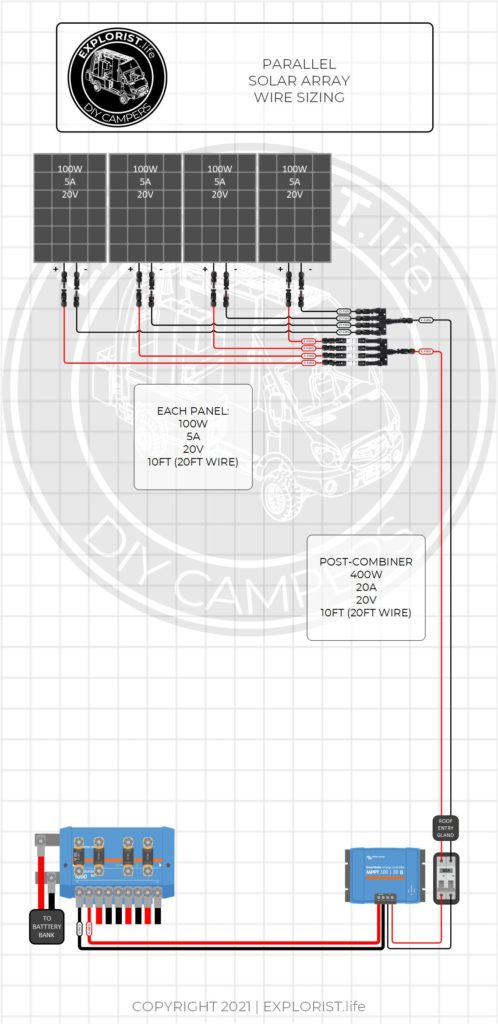
Series-Parallel Wired Solar Array Wire Size
To determine the wire size necessary for a series-parallel wired solar array, we need two separate wire size calculations similar to a parallel wired array. Since the voltage and amperage flowing through the wires before the combiner is different than the voltage and amperage flowing through the wires after the combiner, we need to find the recommended wire size of each.
This means that in the example below, there are 5 amps at 40 volts flowing through the 20ft of wires from each of the solar panel series-strings, 10ft away to the MC4 Combiner. Allowing for a 1.5% voltage drop in the wire sizing calculator, we can see that we can use 16 AWG Wire for these wires.
After the Combiner, since parallel wired series-strings of solar panels get their amperages added while their voltages stay the same, the wires would be delivering 10 amps at 40 volts through 20 feet of wire, 10 feet away to the charge controller. Allowing for a 1.5% voltage drop in the wire sizing calculator, we can see that we can use 14 AWG Wire for these wires.
Try it for yourself. Here are the inputs used:
- For each series-string to the MC4 Combiner
- 5 Amps
- 40 Volts
- 20 Feet of Wire
- 1.5% allowable voltage drop
- From the MC4 combiner to the Charge Controller
- 10 Amps
- 20 Volts
- 20 Feet of Wire
- 1.5% allowable voltage drop
Best Solar Array Wire Size – 10 AWG
A properly designed camper solar array SHOULD always be able to use 10 gauge wire for all wires between the array and the charge controller, and here is why…
Even if the calculator recommends a smaller wire, like 16 gauge… 10 gauge wire is simply more durable from a physical standpoint (think; big rope vs small rope). And since it will be installed on the roof of your camper, out in the elements, having a more durable wire is a very good thing.
This ‘larger-then-necessary’ wire size will also cut down on voltage drop, which will help deliver every drop of power from your array to your charge controller.
Now… What if the calculator recommends a wire size larger than 10 AWG?
If that were the case… I’d take a step back and look at how the array is wired. For an MPPT charge controller to REALLY do it’s job, the array voltage really should be at least 20V over the battery bank voltage. This higher voltage will also keep the array amperage lower, which will let us use a smaller wire size.
How many watts of solar can run on 10 AWG wire?
High-quality 10 gauge wire with 105-degree celsius insulation is rated with a max ampacity of 60A. Most MC4 connectors, on the other hand, have a max ampacity of 30A; so we need to keep the array amperage below 30A; and we can do that by wiring the array in series or series-parallel so the array has a lower amperage and a higher voltage.
This means that with an array amperage of 30A, feeding say… 250V into a big SmartSolar MPPT 250|100… Using watts law of 30A x 250V… this would actually give us an array wattage of 7500W of solar panels; which is a LOT. In fact… that’s about 150% the max rated wattage capacity of that SmartSolar MPPT charge controller when paired with a 48V battery bank. So the wattage of the array…doesn’t REALLY matter when trying to see if we can use 10 gauge wire.
So, if you are trying to design a solar array on your own… use the ‘technical’ methods I taught you earlier to double check that 10AWG is indeed large enough and again… if 10 AWG isn’t large enough… consider re-working your array design to have more panels in larger series strings to boost the array voltage and lower the array amperage so you CAN use 10 AWG wire.
Why not just use larger than 10 AWG Wire?
Generally, the only reason a solar array would need to use larger than 10 AWG wire would be to reduce the voltage drop from the array to the charge controller. Since we are talking about camper solar arrays where the length of the entire camper is likely under 45ft, though… The chances of the wires from the array to the charge controller being over, say, 50-60ft would be rare. On a properly designed solar array, achieving a 3% or less voltage drop with 10AWG wire is easily achievable.

21 Responses
Where do the 15 amp MC4 fuses go in the 1200 watt solar panel array in the 50 amp retro fit diagram? Should they be 25 amps because 300W ÷ 12Vdc = 25 amps. Neither the purchased 50 amp retro diagram nor the website’s 1200W array diagram has them shown. Please help !!
This video shows that: https://youtu.be/b2H8vpj8rQg
i have 8 pcs of 320watts solar panel, 4 pcs 0f 220 amps battery to charge and a 48v solar charger controller. kindly advise how best to connect my solar panels
LOOKING FOR SUGGESTIONS & HELP:
I have a solar system that needs remodeling. It was installed as a short term system but became a little longer use. Then it was partially destroyed by excessive snow fall (roof top system- now it has been removed partially and plans for a single pole mount). I have all the equipment I need (I think) to redesign the system.
1. I own 17 CSUN 310W 72P solar plans (only using 4 at this time in the system). They are currently not installed due to excessive snow fall and damage on roof mount design.
2. Using a 300V 100A MPPT controller.
3. Using a 12V 6000 Watt (12,000 Watt Peak) Inverter (NAPA). Output 50A.
4. Using 8 Batteries 12V 200Ah GEL sealed lead acid. Wired in series at this point in time. (Subject to change for more efficiency.
The location of the system is off-grid high in the mountains of Idaho (lots of winter snow & cold.
I am looking for help how best to design the panels, batteries to function with maximum potential of the charge controller, batteries and solar panels.
I have .pdf files of all the equipment for details.
Any suggestions greatly appreciated.
Sincerely,
Thomas Blalock
For 6000W of inverting capability and 5270W of solar, I’d recommend following my 24V split phase system here: https://www.explorist.life/24v-6000w-120v-240v-split-phase-camper-solar-wiring-diagram/
I know the plan above doesn’t include the specific components you’ve already chosen, but you may have to chalk that up to the “Purchased products without a full plan” tax. You’ll be able to use the batteries wired in series parallel and the solar panels; but that 12V 6000w Inverter is a no-go. Charge controller is probably fine given it can charge a 24V battery bank.
Hi there. I have purchased your 2000W inverter plan. I would like to wiring in and auxiliary input for 2-100W Jackery panels in addition to my 2-200W Newpowa panels up top. What equipment might i need in addition to the controller and disconnect for the Newpowa panels and how would that be wired in?
Thanks
Tom
Here is a wiring diagram and parts list for the 2x200W panels: https://shop.explorist.life/shop/all-products/camper-wiring-kits/solar-charging-wiring-kits/400w-solar-charging-wiring-kit-2x-200w-12v-battery-bank/
The 2x Jackery panels could be wired in a similar fashion to a second charge controller.
Hi Nate!
Do you have any blogs or wiring diagrams available for integrating lithium and solar into an existing system such as an airstream?
Yep! Check out the 30A or 50A OEM RV Retrofit diagram (whichever is applicable to your application) on this page you commented on.
Could not figure out how to contact about issue with buying a wiring diagram. I bought first one, 50amp refit and saw it had a Magnum inverter. I wanted one with Victron 3000 II. Bought that one and changed name when saving it and now I can not access it and I have no idea how do re down load it.
https://www.explorist.life/contact-us/
Hi Nate, I’m sure you have you’ve come across tons of people on your recent tour. I’m the English bloke you’d met in Reno, I was after the plan that you guys had outside on the board.
I believe it was for 2 X 100 BB battery’s. Plan on running 2 x 200 watt solar panels on top of a Transit HR.
Don’t plan on running air conditioning, but will have a microwave along with the other basics of a build.
Sorry if I’m in the wrong spot or if this is something you don’t offer.
Thanks for the advice again,
Andy
Here ya go: https://www.explorist.life/2000w-inverter-200-400ah-lithium-200-to-700w-solar-camper-wiring-diagram/
Hey Nate,
I wanted to ask if this is a fire hazard since 10 AWG wiring is typically rated for 30 amps. This setup is for emergency power to the house with two sub-panels connected to the GoalZero.
Here are the specs:
– 2x Mission Solar 345W Solar Panel (In parallel)
– Short Circuit Current Isc V 10.92
– Open Circuit Voltage Voc A 41.00
– Rated Current Imp V 10.34
– Rated Voltage Vmp V 33.37
– Fuse Rating A 20
– System Voltage V 1000
– GoalZero 1500x Power Station
– 10 AWG wiring at 50ft. (Would like to go shorter, but there’s really only one spot on my property that I can place these.)
At best, I’m able to get 500W of solar and the GoalZero is saying the amp input is 36 amps. My question is should I up the wiring to 8 AWG or is this ok? I’ve been checking the cables every half hour and they don’t feel like they’re warming up at all, but this is my first build so I’m paranoid.
Thanks,
Kendall
Pushing more amps through a wire than it is designed to carry is indeed a fire hazard.
Hi Nate, sorry not RV related. I live in South Africa, I’ve bought a 3kva inverter 24v with 2 325W panels. Max solar input is 75VDC on the inverter. Hence I’ve wired the panels up in parallel giving me an average voltage 35V. Would it be wrong to wire the panels up in series or do you have any other suggestions. I love your YouTube tutorials and they have helped me tremendously. Thanks Ian
I suspect that those two panels wired in series would exceed the max voltage of your charge controller when the temperature drops. This video shows that relationship: https://www.youtube.com/watch?v=MxziHKvTRh8
Hi Nate,
Thank You for sharing your knowledge with us, much appreciated.
I bought 12 AWG wiring for my van build before I bought a 6 Gang Rocker Switch Panel. The Rocker Switch Panel came with 16 AWG wiring. Is it safe to connect the 12 Awg to the 16 AWG together or will it be a fire hazard?
Thank you for your time & effort which is greatly appreciated.
Eric
It’s fine. Use WAGO connectors to make those connections: https://amzn.to/3cNu4Lu
Hello,
If I use your wire size calculator with inputs of I=60A, V=54V, length=6 ft, your recommendation is 10 AWG. The ampacity of 10 AWG is much less than 60 amps. This may cause certain people to install undersized wires in their setup. Just thought you should know 🙂
The max amps of high-quality fine strand wire with 105 degree C insulation is 60A before any derating factors as per Table VI of ABYC E-11: https://www.paneltronics.com/images/technical/E11Excerpts.pdf