
This DIY camper solar wiring diagram and parts list is perfect for ground-up electrical installs into campervans, skoolies, or expedition vehicles. This system is most suitable for systems that do not have a pre-existing house electrical system installed.
This diagram features:
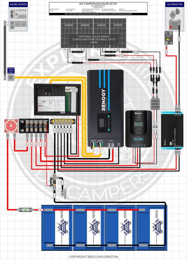
- 2000W Inverter Charger
- 200+ Amp Hours of Battery Storage Capacity
- Up to 520W Solar Array Capacity
- Alternator Charging at 60A
- Shore Power Charging/Passthrough
Not quite what you are looking for? Check out other system setups here: https://www.explorist.life/solarwiringdiagrams
Note from Nate: It’s no secret that Battle Born Batteries and Victron Energy are sponsors of the work I do here at EXPLORIST.life. Both of those brands make top of the line, high-end equipment and in my opinion, is worth every penny.
BUT… I have seen time and time again people trying to design systems with less expensive equipment to fit within their budgets (rightfully so. I get that.) but struggle with budget-friendly system design including proper fusing, wire sizes, fuse choices, busbars, component placement, switches, and everything else necessary to build a high-end system. This is why I’ve made this diagram.
This diagram features high-quality fuses, busbars, wires, and lugs with highly efficient wire routing & system design with decreased redundancies that will accommodate most of the popular and less expensive Inverter/Chargers and other components I see people using like Renogy and AIMS.
This is the Honda Civic of camper electrical systems. It won’t win any high-performance races, but it will get you from point A to point B in a safe and reliable manner.
History of Changes to this Page (Click to Expand)
Post Published Jan 8, 2021
TABLE OF CONTENTS
HOW TO USE THIS PAGE – VIDEO
This orientation video will show you how to best use this page to build your DIY Camper Solar Setup. It’s a quick watch but I think it’s pretty important.
DIY Camper Van Wiring Diagram
DIY Camper Solar Parts – Shopping List
The list below is a consolidated parts list for this entire system (Minus the solar charging leg, which is listed at the bottom of this blog post).
For the ‘Quantities’ in the below shopping list, each singular component is listed a quanty per each, wire is listed a quantity of feet, and heat shrink is listed as qty 1 = 2.25″.
For Example:
Qty 1 – Inverter Charger means you need to purchase 1 Inverter Charger
Qty 3 – 4/0 Wire means you need 3 feet of 4/0 wire. This may mean you need to buy 5ft from the product page
Qty 5 heat shrink means you need 5 pieces of 2.25″ heat shrink. This means you’ll need 5 x 2.25″ pieces of heat shrink for a total of 11.25″ of heat shrink.
Camper Solar Parts Detail
The section below will tell you where each of the parts from above fits into the wiring diagram. This is quite lengthy, but if you are having trouble seeing the diagram or just want more clarification that the diagram above doesn’t deliver, hopefully this will help:
Order of Operations for DIY Camper Solar Install
Coming soon

109 Responses
Nate,
I’m wanting to set up something like this, but I’m concerned about battery charging.
Are there issues with the RV’s Converter, Charger/Inverter, and Solar Charge Controller all trying to charge the batteries at once? I’m thinking of these scenarios (minus alternator DC/DC charging which I will not need):
– On shore power and with the solar charge controller off. Both the Inverter/Charger and RV’s converter will try and charge the batteries.
– On Battery power with solar charge controller and inverter on. Both the solar charge controller and RV’s converter will try and charge the batteries.
– On Battery power with solar charge controller off or receiving insufficient solar power (cloudy, dark, etc.) and inverter on. The converter will try and charge the batteries using power converted from the inverter.
– On Battery power with the inverter off – no issue whether solar charge controller is on or not (of course, only get 12V throughout RV).
I’ve searched all over the place looking for a clear answer and have been unable to find one. I thought about putting a diode on the RV’s converter to battery connection so that the battery can only supply the RV’s converter and charging will only come from the inverter/charger or the solar charge controller, since both the inverter/charger and charge controller can be switched off. This will ensure the 12V circuits in the RV always have power. Leaving the RV’s converter out of the battery charging business (mine is an older pre-lithium model) will also save me the cost of updating the converter.
Thanks for all the info you provide.
This diagram shows how to integrate these types of systems into an OEM rv with preexisting electrical: https://www.explorist.life/30a-camper-inverter-with-solar-and-alternator-charging-wiring-diagram/
Hi Nate! What all would I need to change on this budget friendly set up to use the 3000w Renogy inverter rather than the 2000w Renogy inverter?
2/0 wires (and the associated lugs and heat shrink) to 4/0 wires. 250A fuses to 400A fuses and upgraded fuse holders. Fused busbar to Lynx Distributor. Minimum of 400Ah of batteries.
In material list you have an add a fuse kit. Where does that go?
It’s for the signal wire from the OEM fuse panel that feeds power to the sig termal of the DC DC Charger.
Hey Nate,
Bought one of your wiring diagrams and it has worked great. I do however have a question, the 100ah batteries I am running (Weize) are limited to a chain of 4. Is there a way I can wire in an addition bank of 4 batteries for a total of 800ah? Using you 50 amp Rv retrofit Solar upgrade diagram. Thanks in advance
Sounds like a great question for the manufacturer. I know that Battle Born batteries do not have that limitation, but I don’t know about the batteries you’ve chosen.
@Nate Yarbrough, Dude I have no problem with anyone making money anyway they can but BATTLE BORN BATTERIES is borderline making you look corny and like a prick at the same time. I learn alot from the stuff you put online. So you know a lot more about electricity period than I ever will. But I could have told that guy yeah the batteries will probably work. But to make sure you can ask the manufacturer. They gonna pay you anyway. Just my advice. Thanks for help for real
Chris, remember… you are coming to MY comments section on MY blog post on MY website. If you don’t like the way I answer questions, you can always navigate to another website, and I’m sorry that you are having a bad enough day that my responses caused you enough frustration to call me a prick. I don’t know you and I don’t know what you are dealing with, but It’s very important to me for you to know that I don’t care what you think of me and giving proper answers to the best of my knowledge is infinitely more important than making odellchris52 think I’m ‘not a prick’.
Thank you for the diagram!
Eventually I will do the entire system but right now I am only wanting to charge my battery on my travel trailer. I already have the Renogy 40A charge controller. It seems to me that I would just exclude the additional items connected to the busbars and relocate my existing wires connected to the batteries to the busbars correct?
Sounds like you are wanting to remove/change quite a few different things from this system. For this reason, I can’t give you the go-ahead as there are usually many considerations to changing an electrical plan.
Hi Nate, I have an AIMS inverter 3000 Watts. I have hardly used it as I just started traveling with my van. The inverter is now beeping constantly. I have checked all the connections, and the batteries are fully charged. The inverter is not hot either and there is nothing plugged in (so it is not in overload). What else could be wrong?
Thanks!
Monica
I would recommend reaching out to the manufacturer for tech support for troubleshooting on that unit.
Hi Nate,
Your info is super detailed and helpful. I bought this diagram pdf and was wondering if you could help clear some additional questions I have.
1. I only have room for 3 solar panels (300W), would I have to change anything in the diagram? Solar charge controller maybe?
2. If I run solar panels in parallel vs series, like you show in the diagram, would I seriously miss out on anything and would I need to change something in the diagram?
3. I am planning to run 2x200Ah BattleBorn LiFePo batteries, total of 400Ah instead of 4.. How would this change my fuse amperages?
Thank you for your help and any comments.
Paul
1: Nothing would change.
2: Run the 3x panels in series.
3: Fuse sizes don’t change as battery bank capacity changes; so no changes needed there.
Hi,
Thank you so much for this! It’s an absolute life saver!
I can’t find the WFCO AC-DC Distribution Panel (I’m in the UK), I have been able to track everything else down (I think)! Any suggestions for an alternative that I can get in the UK that will do the same thing?
Was also wondering about an upgrade to the simarine pico monitoring system so I can have the battery and water tank stats in one place. Would you recommend?
Here are the ‘updated’ distribution panels (AC and DC): https://shop.explorist.life/product-category/all-products/distribution-panels/
Although I’m not sure how useful the AC panel would be for you in the UK with the 230V power you have over there.
The Renogy B2B charger is supplying power to all the systems when the vehicle is running. The battery shutoff located before the buss bar only stops the power to the batteries, not everything else. Is that what is supposed to happen, or am I missing something?
That’s correct. The B2B charger is trying to find something to supply power to when the batteries are disconnected, so it’s powering the ligts/fans/etc.
Hey Nate,
Any idea when you will have the “Order of Operations for DIY Camper Solar Install” or can I use one of your other “Order of Operations”.
Thanks,
Rod
The other ones will work fine. Also consider watching this video for another option: https://youtu.be/01F4QDVJUq0
Really confused – 10 awg or 6 awg for inverter to AC distribution? Also, is this number effected if I don’t have the inverter charger and just have a normal 2000w sine wave inverter?
10 for this specific wiring diagram. The 6 AWG is for the Victron Multiplus units. The wire size would indeed change if you are changing the equipment used. I have a list of compatible equipment in the product list on this page.
Hi Nate. Your information is highly generous and valuable. Thank you so much. I’m tempted to buy your Budget Friendly diagram (2000W INVERTER | 200-400AH LITHIUM | 200W-520W SOLAR CAMPER WIRING DIAGRAM). Or do you recommend another diagram if: 1) I would like a 15A plug for the shore power charger, knowing this could considerably slow down the batt charging time. 2) I bet That would mean another inverter (still pure 2000W though), and 3) I’d like to start off with 100Ah Battleborn. All this in order to slowly ramp up to a full 200Ah batt system and about 400W of solar). All other components you recommand would stay the same, so that they are ready for the above final system. Mind you that when all is done, I would definitely want to keep the 120v 15A shore power configuration. THanks
I don’t recommend 15A shore power. Install 30A shore power and then use a 30A to 15A adapter when only 15A shore power is available: https://amzn.to/3d7J6vx
@Nate Yarbrough,
Awesome Nate, thank you so much.
I looked up the specs of the Charger/inverter you recommend. It seems I can set a maximum shore power current draw in order not to cause trouble when hooking up at a friend’s house for exemple (15A regular 120V socket). That said, I’m purchasing your Budget Friendly diagram shown above!
One more question…the PDF I purchased prints with a black background. Do you have a version with a white background so I can add notes to my copy?
Thanks,
Kathy
All of my diagrams are designed to print with a white background. Probably a printer issue on your end? Perhaps convert from PDF to JPG and give it another go.
Hey there,
I bought the Budget Friendly diagram. You don’t list the SOK LoFePo battery as an alternative. Can it be used in place of the Battle Born?
Also, adding shore power is optional, right?
Thanks!
SOK can indeed be swapped in place.
Shore power is required.
How would recommend installing a separate breaker box for the 12v system and 120v system if you can’t find a combined unit? (Sadly the suggested one isn’t available in canada.
Good timing. These panels have been impossible to find a good source for, so we’ve taken matters into our own hands and bought a pallet-full of them. I literally just pushed the ‘publish’ button on separate AC and DC panels that we have in-stock. Check them out in our store here: https://shop.explorist.life/product-category/all-products/distribution-panels/
Thanks Nate! This page is a life saver! I bought everything on this list and will be starting the electrical buildout on my Skoolie in a couple weeks. Any idea when the order of operations section will be up? I am DEFINITELY going to need it!
Check the order of operations on this page. It’ll be the same: https://www.explorist.life/3000w-inverter-400-600ah-400-to-1200w-solar-camper-solar-kit/
could I substitute a Victron 100/50 charge controller into this system and expand to 6 100-watt panels? would any of the fuses or wires need to be changed? Thanks!
Yep! Here are the wire/fuses/etc necessary for 6x100w panels: https://shop.explorist.life/shop/all-products/camper-wiring-kits/solar-charging-wiring-kits/600w-solar-charging-wiring-kit-6x-100w-12v-battery-bank/
How would I connect shore power and a Renogy PSW inverter to the wfco-8935? Do I need a separate transfer switch?
Don
You’d need to change quite a few things from this diagram. I recommend using the parts as shown in the diagram.
Great info – is the 250a mega fuse on the + side sufficient for using 600ah of AGM for battery bank [3 x 200ah]?
The fuse size doesn’t change regardless of the battery bank capacity.
Hey Nick got a quick question for you can you substitute the mega fuse busbar in this budget build with the victron lynx distributor
Yes! Absolutely.
Hi Nate! We are super happy to have found your website. So we have purchased everything to complete our build, including your wiring diagram, but haven’t purchased the “Victron Fused Busbar.” The amazon ratings aren’t great and many negative experiences, including melting have been reported, making us nervous about that particular component. Do you have a substitute for this component?
Sure! Go with the Victron Lynx Distributor like shown in all of the other diagrams on this site: https://amzn.to/3iCQZg8
@Nate Yarbrough, Appreciate everything you have done to help the DIY community build out these solar setups. Thank you.
My question:
1. With the above wiring diagram are you saying we can swap out the busbars for a Victron Lynx Distributor? No other adjustments needed?
2. I’m thinking of subbing in a 3000W inverter/charger vs the 2000W. From reading the manual I know the wire gage leading from the inverter to the busebar/Lynx Distributor needs adjustments from 2/0 to a 4/0. Would other wire gages be impacted by this move?
1: Correct.
2: Swap 2/0 Wire for 4/0 and swap 250A fuses for 400A fuses (and upgrade the main system fuse holder to the heavier duty one: https://shop.explorist.life/shop/all-products/fuses-breakers/anl-fuses-fuse-holders/anl-fuse-holders/anl-fuse-holder-with-insulating-cover-35-to-750a/
hi
Good stuff.
A couple of questions:
(i) I was wondering why the PV to MPPT breaker is so large: 63A for 2×2 series-parallel 100W panels — Using the Rich panels you link to: they have Isc=5.93A so x2 = 11.86 x 156% = 18.5A; 18.5A vs 63A is a big jump?
(ii) if the MEGA fuse to the DC side of the panelboard is 100A, that means #3 (or #2) (Cu %75degC) not #6?
thanks!
1: Explanation of that can be found on this blog post: https://www.explorist.life/how-to-wire-a-solar-disconnect-for-a-diy-camper-electrical-system/
2: 6 AWG fine stranded wire with 105 degree C insulation like recommended in the parts list here has a max ampacity of 120A per ABYC, so a 100A fuse is well within reason.
Hello Nate! Thank you for making electrical less intimidating!Quick question, on the 6-way fuse holder there are only 5 that are connected via the copper bus bar. In your diagram the farthest left posts are unused, is there a reason for this? Just wondering if I could use them or how to use them. Thanks for all your help!
That could be used for a load/charger you wanted to be switched on/off separately from the items on the busbar. That is purposefully left unused in this diagram for the sake of simplicity.
Hi Nate! Thanks for all your time, effort, and correspondence for all our newbie needs. My question is why do you recommend a separate solar controller and dc/dc charger when the renogy 50-Amp Charge Controller Item #1858273Model #RBC50D1S-G1 can do both, with solar priority? Does it come down to efficiency? Also im outting my 07 Tacoma with 200w solar to run lights, fridge and laptop, the shore power connector seems more suitable for an RV type application. Could i just get by with a reg extension cord to charge up and float charge when needed?
Thank you
The DCC50S combo MPPT and DC DC charger only has a max of 25V input from solar. This is too low for most arrays. I also don’t see how an MPPT charge controller can even have a max voltage that low as it would force you into wiring panels into parallel AND would greatly handcuff the charge controllers ability to sweep for an optimum voltage. Basically… and IMO… it’s just a terrible design that I feel they are just trying to market as ‘easy’.
@Nate Yarbrough,
Thanks for confirming this. I was also looking at just using the one unit, but have heard some concerns over the max 25v input.
Hey Nate,
Super helpful info here. I have a question regarding the 60A DC-DC Charger. Is there any worry with a 60A pull that too much strain is put on the alternator? I’m thinking of downgrading to the 40A to be a little safer as I’m driving an e350. Are there any precautions you would recommend taking to protect the alternator?
Thanks
Ultimately, the harder you work the alternator, the faster it will wear out. There’s no metric to determine ‘how much faster’ a 60A draw will wear out your alternator than a 30A alternator. If you wanted to be the ‘most safe’ for your alternator… don’t charge from your alternator.
Hey Nate!
I bought your schematic after ordering everything on your parts list for the
2000W INVERTER | 200-400AH LITHIUM | 200W-520W SOLAR CAMPER
I’m going to install it now and I noticed a parts list fuse is different from what you have in the schematic. It is the Busbars to “Solar Charge Controller” section. Parts list I ordered from says 60A fuse. Schematic says 50A fuse.
Will this make much of a difference?
Side note: 2-to-1 MC4 combiner link is no longer working so you are missing out on some click purchases…
Also, I have the 40A DC to DC charger from Renogy.
Will the 80A circuit breaker you have recommended for the 60A charge still be ok or do I need to downsize that?
Looks like they recommend 50A to house battery in the manual but they also recommend 75A breaker for the 60A charger instead of your recommended 80A breaker.
Cheers,
Daniel Johnson
60A vs 50A won’t make a difference. Just use whichever is available. 50A fuse is the ‘most correct’ but is hard to find in a MEGA fuse which is why there’s currently a 60A fuse in the parts list.
Downsize from 80A to 60A for your DC DC Charger.
Sometimes we have to go against manufacturers recommendations when a given fuse size is not available. For example… a 75A MEGA fuse doesn’t exist, so we have to go with whatever is closest given that the fuse size does not exceed 150% of the max ampacity of the wire the fuse is protecting.
Hi Nate,
Thank you so much for all the insanely in-depth information you’ve created here. I’m sorry if this has already been answered in previous comments, but do all the wire gauge sizes, fuse sizes, etc. change if I am only using two 100Ah batteries instead of the four used in your diagram? Second, Im already in possession of a 30A Renogy Wandered PWM charge controller, would this substitute properly for the 40A Rover? (I know I will lose efficiency using my device over an MPPT, but I’m willing to take the loss)
Thanks a ton!
Wire and fuse sizes wouldn’t change regardless of battery capacity.
For the 30A charge controller… You’d just want to check the max wire terminal size on the charge controller and adjust from there for wire/fuse size.
Will this system still allow for DC lighting? It seems to be geared towards converting everything to AC and charging Batteries or am I missing something?
It will DEFINITELY allow for DC lighting. This system has a 12V DC Fuse block that can handle 15 separate DC circuits.
Hi Nate,
Best website I’ve seen so far for camper solar systems! I’m a bit confused about battery nomenclature. I’ve seen reference to lithium batteries, lithium ion batteries and lithium iron phosphate (LiFePO4) batteries. Are these all the same animal?
Thanks
They are all technically different but anytime you see “Lithium” referred to on this site, it will always be Lithium Iron Phosphase (but I’m never going to type all of that out).
Hi Nate,
Can I use 150AH 12v LifePO4 for my 2000 watt inverter? I am really only using the inverter for a 1200w microwave which will only run for a few minutes at a time, 1 or 2 times a day. Or should the Battery WH exceed the inverter?
I could probably use a 700w microwave with a 1500 w inverter.
Thanks,
Casey
Any less than what I’ve recommended in this blog post will yield inconsistent results and I, therefore, cannot recommend less than minimum stated here, which is a minimum of 200Ah.
Nate,
Thanks so much for all the good info. I have purchased your 12v DC and AC diagrams along with DIY Campervan diagram. I want to use the Kisae (DMT1250 DC-DC & MPPT charger and Kisae inverter/charger 2000W) Can you show a diagram where these are implemented? Happy to buy the diagram again if these were in place.
Thanks!!!!
MG
The Kisae inverter/charger should be able to just be able to be substituted in place.
The DC-DC & MPPT charger would take a bit of changing up, but is something I don’t have a diagram for, so you’ll have to do your due diligence on that, but you can use my diagram as a base. Just be VERY cognizant, that the solar input on this unit is only 30-something, so wiring solar panels in series or series-parallel like I show in my diagrams is NOT acceptable.
@Nate Yarbrough,
30-something what? voltage or amperage input from the panels?
I also am planning to use the Kisae (dmt1250 dc-dc mppt)
with 3x 220W (48VoC) panels in parallel, I’ve been told that the max voltage the kisae can handle from the PV input is 50V. Will I have a problem with that setup?
30-something volts.
You will indeed likely have issues. Those panels will put out a higher voltage when the temperature drops. More info: https://www.youtube.com/watch?v=MxziHKvTRh8
I am trying to do my best to replicate this electrical system in my van build but I had bought a Victron battery monitor. Where would I connect?
The Victro BMV-712 would take the place of the Victron SmartShunt in this diagram. It’s nearly the same piece of equipment.
@Nate Yarbrough, Okay thank you so much! I appreciate your help!
I purchased your diagram 2 months ago and you were referencing all Victron products. Is there a specific reason that you switched to Renogy now? I was just about to pull the trigger on Victron, but now I’m questioning it. (2000W inverter package)
The diagram with the Victron components is still the far superior system: https://www.explorist.life/2000w-inverter-200-400ah-lithium-200-to-700w-solar-camper-wiring-diagram/
I do NOT recommend Renogy components over Victron. I made this diagram for those who are looking to pinch pennies by using lower end components but still come out with a safe system with proper busbar & wiring planning.
Quick question regarding an enclosed cargo trailer conversion, with a 2200w inverter references grounding to the chassis (ie trailer) – do you know if this will have a negative impact if boondocked, (and connected via 7pin to tow vehicle) would there be any kind of problem? Or would a very easy solution be to just unplug the 7pin trailer wire from tow vehicle when boondocked and using inverter power? The whole electrical system of the trailer will be stand alone, except for this one bonding point. I want to make the trailer and tow vehicle isolated from each other if possible.
The chassis ground should indeed be grounded to the chassis. Isolating the tow vehicle and trailer chassis grounds is not necessary.
AWesome! Thanks for this.
No problem! Glad it helped!
Hi Nate,
Thank you SO much for this amazing resource! I was about to order the Victron 6-Way Mega Fuse Holder w-Busbar you link on this guide, as it seems like a great way streamline things. However, my system is much smaller than the one diagramed here (no inverter or shore power– using DC only to run lights, fans, etc) and I realized that I couldn’t find any 40A MEGA fuses. Do MEGA fuses smaller than 100A exist? Or do I need to just use ANL fuses or circuit breakers instead? Many thanks!
The smallest MEGA fuses are 60A. Without knowing the rest of your system… you may just need a fuse block like this: https://amzn.to/3tqlARk This is the best way to fuse things like lights/fans/usb outlets.
Hi, Nate.
I see you recommend the WFCO AC-DC Distribution Panel, $120. At one point you recommended, and made a video for, Arterra WF-8930 $75. Will you please explain why you’re no longer recommending the less expensive Arterra? Also, is the WFCO connected the same as you had explained in your Arterra video?
Thanks!
They are the same. I likely switched due to one being out of stock or something.
Do you have a recommended cutter and crimper for the large diameter wires?
Yep! Check out the ‘cutting’ and ‘crimping’ videos on this playlist: https://www.youtube.com/playlist?list=PLmvhcyi4n0TUjVGA_O5aI5SQrS1kKLgEF
The actual tools I recommended are listed in the video descriptions.
Hi Nate, thank you so much for these diagrams. They have been unbelievably helpful!
I’m curious why you have a fuse on both sides of the master disconnect. Couldn’t you just connect the master disconnect directly to the top bus bar on the mega fuse block since there is already a fuse in between the master disconnect and the battery?
Theorhetically, yes… but the wire just simply won’t fit. The fuse in that location is a bit irrelevant/redundant, but is how we have to do it.
@Nate Yarbrough, Thank you so much for these amazing tutorials!
What do you mean by “simply won’t fit”? do you mean there is not enough space for the cable to be connected on the top bus bar on the mega fuse block?
Correct
Thank you for the detailed information you provide. I purchased the Renogy 400 watt premium kit for TT. I understand that I don’t need all the components listed for the budget friendly system. I have two questions. It appears that you have wired the solar array in series parallel, which is what I intend to do. You see any issues with doing this? I will not be installing a DC to DC as I am using Trojan flooded solar batteries (229A). Do I need to make any changes with the fuse ratings? I will be installing an inverter charger. Thank you.
Series-parallel for the panels and charge controller in the parts list is indeed the best way for those panels and that charge controller.
For fuses & such… If you start straying from my diagram and parts list, you need to start doing more due diligence into what needs to be changed to accompany the changes in components. If you are ONLY changing batteries, you do not need to change fuse sizes.
Nate, Thanks for this overview and diagram. I have two questions. First does the Renogy inverter have a built-in transfer switch. Second, with lithium batteries is there any need to pull 12v off of the 7 pin system since the v is too low to charge them, and for that matter if you have solar what’s the value of a DC to DC charger. Just trying to get it all straight in my head as I’m getting close in my airstream Reno to this step. Thanks again.
The Renogy inverter does indeed have a transfer switch built-in.
The DC DC charger would allow you to charge your battery bank from the alternator while driving when the sun is not shining. I generally recommend avoiding this on tow behind vehicles as it requires running new wire ALL the wat to the vehicle starting battery (the wire in the 7 pin connector is too small).
I am building a small (4′ x 8′) teardrop trailer and space is very limited. Would a smaller distribution panel work with this same setup? I was thinking the WFCO WF-8735-P Black 30 Amp Power Center – https://www.amazon.com/WFCO-WF-8735-P-Black-Power-Center/dp/B004LF14Q4/ref=sr_1_1?dchild=1&keywords=WFCO+World+Friendship+Company&qid=1611089515&sr=8-1
I purchased the High Res photo and the DC circuit workbook and am looking forward to getting the electrical system up and running for my trailer.
Thank you.
Derek
I suppose that one would work, but it’s only an inch smaller in all directions than the one I recommend in the parts list but sacrifices a half dozen DC circuits and you would need to disable the converter.
@Nate Yarbrough, That’s a great point. Another question I had was how would I connect the DC-DC battery charger to the alternator, since I am using this in a trailer set-up and not in a van or camper? Would I use the black wire of my 7-Pin trailer harness or is there another way? Thanks for all the work you have done giving rookies like me somewhere to turn for this information.
Hey Nate. We’ve purchased everything off of your budget friendly list as well as the pdf diagram. We’re complete novices in all of this, so bear with us… I don’t see a “standard” breaker box, so I was wondering where all of our regular outlets will wire into? Thanks in advance for your help and more questions may come later. I also had a question regarding the fuse kit, but I believe it’s answered in a post below.
The breaker box is in the top left corner in the diagram. Listed as WFCO AC DC Distribution Panel in the parts list: https://amzn.to/2KX9IAz and here’s a tutorial for how to wire it up: https://www.youtube.com/watch?v=YiufFMKolpY
Hi Nate. I have a 2000W inverter already, but if I go to 400 or even 600 amp hrs of BattleBorn batteries should I go with a 3000W inverter? My AC power needs would be an induction cooktop, AC/DC fridge, coffee maker, and a micro/convection oven. My AC draw would be below 2000W at any one time, but if I have the battery capacity would I be better off with a bigger inverter?
If the 2000w inverter is working fine for your needs, I see no reason to upgrade.
hi nate
your videos etc are so good i just dropped close to $3K buying parts from your list
i did NOT buy the Add-A-Fuse Kit. i don’t see it in the wiring diagram and don’t know why it’s on the list
can you explain, please?
That’s needed to connect the DC-DC Charger to an Ignition positive wire. The info for that connection is included with the user manual for the Renogy DC-DC Charger.
@Nate Yarbrough, thank you!
First of all thank you for all of the time and energy put into all of these diagrams. Your videos are very informative and make something complex simple to understand. I intend to buy all my install stuff thru your links. I also wait thru ads on Youtube so you get the most from them. I wish I could support by buying a wiring diagram but none fully apply to my situation. I am a little unclear of how the wiring would work of you don’t have a combined inverter\converter. All of your diagrams have inverter/converter. I already have a separate converter/charger and inverter. I understand that the converter charger should be disconnected from the system when pulling energy from the batteries. So that it is not a loop. I have a transfer switch for inverter/shore. Would that output from the transfer switch go direct to the OE dist panel?
Thanks
Thanks for the support! I generally never recommend a seperate inverter and seperate charger, that’s why I don’t have a diagram covering that. Here’s how I would recommend doing that with the power distribution panel I’ve got listed above.
Shore power -> Transfer Switch Primary -> AC Breaker Box
Battery Power -> Inverter -> Transfer Switch Secondary -> AC Breaker Box.
From there, you would need to find a way to power your battery charger via, perhaps a dedicated outlet wired to your shore power connection to charge the batteries from shore power only.
I can’t seem to access the ‘Tutorial Video’ on any of these diagrams. Am I missing something?
Also, is the first long list of items the ‘master list’ and contains all the parts needed for this diagram?
If you have an ad-blocker, sometimes that makes the videos not work.
The first long list is indeed the consolidated list of all parts necessary to make this setup shown in this diagram.
Nice explanation. I am wondering if there is an alternative (user friendly) to the MC-4 connectors? We provide small PV panels (flexible) in the 100-120 watt range with a 20 ft cord (#10 PV) so the panel can be positioned in the field for best sunlight. MOst people have an issue with the MC-4…is there an easier slip fit alternative?
I would investigate Anderson connectors or SAE Connectors to make the portable panel wire to camper plug in interface.