There are many different sizes, shapes, colors, and ratings of wires. It’s pretty confusing. For this blog post, I’ll teach you to size wires for a DIY Camper Electrical setup and point you in the direction of the wires I recommend. Sizing the wires for your camper solar setup can get super complicated…if you let it. So don’t let it…
Quick note before we get started. This is just one part of an overarching “How to Install a DIY Camper Van Electrical System” series. If you’ve just stumbled on this article directly without seeing that, there are likely some things we’ve already covered. If you want to check out that step by step guide, you can do that here: https://www.explorist.life/diy-campervan-solar
Also, we have interactive solar wiring diagrams that are a complete, A to Z solution for teaching you exactly what parts go where, what size wires to use, fuse size recommendations, wire lug sizes, and all kind of other stuff to help save you time and frustration. You can check that out here: https://www.explorist.life/solarwiringdiagrams/
How to Size Wires for your Solar Setup
- Step 1: Read the instruction manual for the item you are attempting to wire. Seriously… most of the time it tells you exactly what size of wire and fuse to use. Trust it. They’ve got electrical engineers backing those numbers.
- Step 2: Use my wiring diagrams. I have read those numbers found from step 1 and applied them to my wiring diagrams.
- Step 3: Figure it out yourself. Which is what we are going to talk about now.
The following chart may look familiar if you’ve already been trying to find an answer to the question”How do I size my camper van wires”. This chart, though, is a little different.
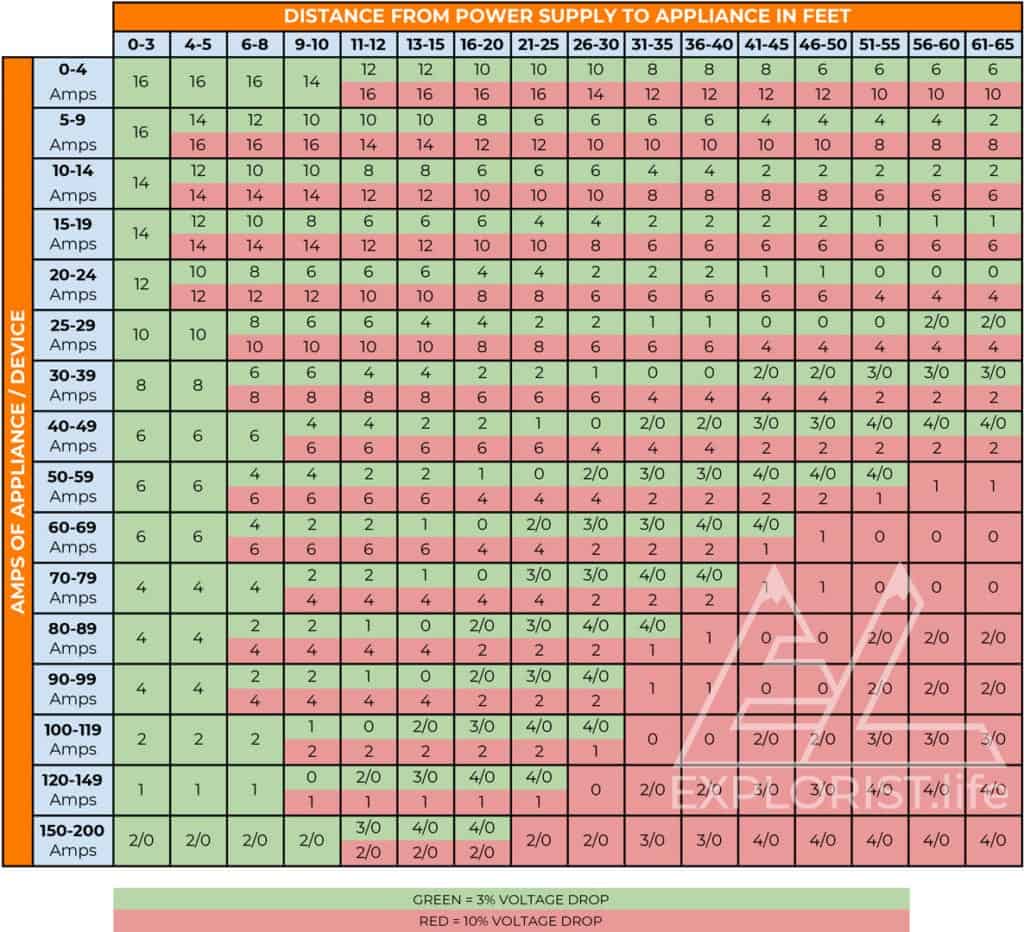
I didn’t like most of the diagrams already out there, so I made my own. Here’s what you do.
- Determine how many amps will be flowing to your appliance. Find that number in the column on the left.
- Determine how far your appliance will be from your power source. Find that number on the top row.
- (not round trip… this graph accounts for that)
- Follow the column down and the row over to the appropriate box.
- The two numbers are the wire gauges that will work for that run of wire.
- Green = 3% voltage drop
- Red = 10% voltage drop.
- Try to stay closer to the ‘green’. Red is still fine, but only for “Less important” things such as fans, lights, usb outlets, etc.
- Consider ‘green’ as the Ideal wire gauge.
- Consider ‘red’ as acceptable, but really try to go for green…
DIY Camper Electrical System Cheat Sheet:
Please verify using the above guidelines, but these wires will work for most situations.
- Battery to Bus Bar
- Bus Bar to 2000w Inverter
- Solar Panels wired in Series to Charge Controller
- Charge Controller to Batteries
- Varies Widely
- Accessory Wire (Lights, Fans, USB, Etc)
- 12ga Duplex
Pro Tip: Be flexible in your wire sizes, if you need 3 feet of 2ga, 4ft of 4ga, and 4 ft of 6 ga; consider using 2ga for all of it and just buy a longer section of 2 ga rather than buffet style wires.
Now that you know what size of wire to use in your DIY camper van electrical system, it’s time to learn what type and size of fuses you’ll need to make sure your system doesn’t catch on fire in case of malfunction. Check out how to size fuses here: https://www.explorist.life/what-size-fuses-to-use-for-a-diy-camper-electrical-setup/
Everything that you are learning here is put to use in our FREE Interactive Solar Wiring Diagrams. If you haven’t yet, check them out as they are a complete solution for a camper van electrical system. Check them out here: https://www.explorist.life/solarwiringdiagrams/
Remember, this is just one part of a full camper van electrical educational series. To see all of the individual guides, click here: https://www.explorist.life/diy-campervan-solar
Finally, If you found this guide helpful, It’d truly mean the world to us if you’d share it with somebody who can use it, pin it to pinterest for later reference, or share it to a facebook group when somebody has a question about this subject. Click the bubble in the lower right corner to subscribe to be notified of future updates and as always, leave any questions you’ve got in the comments below.

24 Responses
Hey Nate,
Thank you so much for all the information you provide! I’ve purchased everything on your list except the wires from batterycablesusa.com. I’m just curious why you chose those instead of others I’m seeing on Amazon for a significantly lower price. Can you provide insight as to how the quality difference justifies the price.
The ones from BatteryCablesusa are a bit higher quality and you have the option of having them pre-crimp lugs onto the wires, which was a requested thing from me… but more importantly… Sellers on Amazon have struggled to keep wire in stock, which makes my parts list… less than useful. Batterycablesusa is a more reliable source.
Hi Nate,
First I would like to say I have been following your work for a while now, your content and ability to present concise, clear, and informative information is unmatched. Thank you for all the help you have provided over the years via sharing your knowledge.
I have a bit of an odd ball question I am hoping you can help me out with. Here goes:
I purchased an RV new from the factory, I asked them to run a 6 gauge wire from the roof solar panel (single panel) to the charge controller and a 6 gauge wire from the charge controller to the battery bank. This was due to the fact I was going to expand the solar system substantially and I wanted to not have to re-run wires or put any holes in the roof. I got my RV and unfortunately they only ran the 6 gauge wire from the charge controller to the battery. The solar panel to the charge controller wire (10 gauge I believe) is about 5 feet in length, and the wire from the charge controller to the battery (6 gauge wire) is about 11 feet in length (could be shorter I am overestimating for caution).
I want to put a something like this https://www.voltlighting.com/ace-connector-2-pack-awg-8-18 to join the wires (if you don’t want to click the link I understand, so I will explain). When I say join the wires I mean take the 10 gauge wire off the charge controller and connect it to the 6 gauge to basically extend the wire. That wire would then be a 10 gauge wire 5 feet long connect to a 6 gauge wire 11 feet to make a total of 16 feet wire that would ultimately be the wire going from Solar Panels to the Victron 150/100 charge controller. Then a 6 gauge from the charge controller to the battery bank. I plan to ultimately have a 4s3p setup with 13.39 volts per panel and 9.21 amps per panel so that would make a 53.56v 27.63a system. I realize the charge controller I bought is overkill but want to be able to add more panels on the ground and more on the roof of my RV so went with a bigger charge controller.
Back to the question finally, will this wire setup be substantial for the current load above of 4s3p? I was not able to figure out how to mathematically figure out the change in gauge along the path to tell if this will be sufficient in my setup. I am trying my best to not have to re-run the wire on my roof as all the panels are flexible and do not require any holes in my RV roof, which I am terrified of doing on a new RV 😊. Years down the road I will be adding additional panels and then I think I will have to replace the wire, but for now to support the 1,474 Watts of power my 12 panels will provide (max) I am trying to avoid running new wire.
Panels are the FXT24R and FXT24L by Merlin Solar – 115w flexible panels
Thank you!
Hey Cory!
Okay… I’m going to sidestep your question a bit…because it’s not necessary to use 6 AWG from a solar array given the array is properly configured. My recommendation… Wire that array 6s 2p into a 2-1 MC4 combiner and run that through the 10AWG wire to the charge controller. That would be about 96Voc and would knock your array amperage down to 18A. That would be well within amperage spec and the boost in voltage would get rid of any potential voltage drop for a 10 AWG wire.
I would recommend making the 6 AWG from charge controller to Battery bank larger, though. Feel free to run the numbers, but I always run 2 AWG for that circuit as that is the biggest wire that the charge controller can handle.
Hey Nate, thanks for all the resources. I’m a little confused between the wiring chart and the calculator. I’m looking at my shore power inlet wire for example: When I calculate 20′ at 30 amps at 120 V using the calculator, it tells me 14 AWG. However, the chart would tell me 6-8 AWG. Seems like a big difference. When I look up some “standard” charts for NM-B, it tells me 10 AWG for 30A service. Is there a mistake in the calculator? 14 gauge seems way too small for 30 amps. Thanks, Steve
AC and DC wiring is a little different. This blog post (and my calculator) are for DC wiring. For AC wiring & sizes… it’s much easier. This blog post explains: https://www.explorist.life/how-to-wire-120v-ac-circuits-in-a-diy-camper-van/
Nate, I am hung up because I can’t arrive at a consensus on the size and type of wiring for the A/C side of the system. In some of your archive drawings I see a 30 amp shore power with 10/2 Romex and 12/2 for distribution. You referrer to an automotive electrical code saying that stranded wire must be used. Isn’t Romex synonymous with solid copper core?
Correct. This blog post should address ALL of those issues: https://www.explorist.life/how-to-wire-120v-ac-circuits-in-a-diy-camper-van/
Hi Nate! I’ve asked a few questions on different articles here. I have a tentative diagram drawn up, but I feel uncertain on a couple things relating to wire and fuse sizes. Maybe the answer to this question will clarify things in my own diagram. As an example: your 2000w INVERTER | 200-400Ah Lithium | 200 TO 700W SOLAR Camper Wiring Diagram shows that you use a 2/0 wire from the batteries to the busbar with a 300A fuse. Looking at an online ampacity chart, 2/0 wire is rated for 175A. If the fuse is supposed to protect the wire, why is the fuse so much larger than the ampacity rating of the wire?
Hello Nate,
I’m currently working on a van conversion and I’ve been using some of your tools and tips to tackle the electrical side of it. Thanks for all of it btw. It helps.
While using your solar charge controller calculator to estimate the max amps that would come from my solar panel to properly size my wires, I’ve come across some rather weird results that didn’t match my own calculations.
I only own one 400W panel with 75.6 Voc and according to your calculator, I could get up to 86V and 33A @ -30°F. How does that even make sense, that would make around 2800W.
I’m fine with the 86V, I had the same result, but my calculations gave me 5.44A.
My spec are as follows :
400W Pnom
12V Battery voltage
-30 °F Estimated Low Temperature
25°C STC
75.6 Voc
Voltage Temp Coef = -.23386 %/°C (It is listed as −176.8 mV / °C in the spec sheet, that I converted myself)
-.29 %/°C (Temp coeff of Pmax)
With only 1 panel in the array.
(Specsheet is available here : https://www.sunpowercorp.co.uk/sites/default/files/2019-12/sp_MAX3-400-395-390_ds_en_a4_mc4_532418B.v4.pdf)
Am I missing something ?
I understand that I would get 33Amps AFTER the solar charge controller, but how could I get that kind of Ampage before it ?
Cheers,
Frédéric
The ‘max amps per panel’ figure on that calculator is for the ‘after the charge controller’ number. The calculator doesn’t take into account the amps before the charge controller.
Hi Nate,
Great you are doing this and I hope you can help me out.
I bought a motorhome so i can use it for work I’ve been told 150w 12v panel will be enough to power my fridge 24/7, lights and TV?
What gauge wiring should I use to connect my solar panel to the charge controller? And what gauge to connect the 2 batteries to the charge controller? And what fuses will i need? Will i also require a bus bar and maybe a voltage sensitive relay or is that going over board?
If you could answer these that would be amazing. Thank you in advance.
Mr T
Sure! I have a whole suite of wiring diagrams that should answer all of those questions: https://www.explorist.life/solarwiringdiagrams
Hi Nate, Thanks for your great tutorials and information.
I have a question; why are the wire size calculator results much different then the tables on this page?
Am i doing something wrong?
Without knowing what parameters you are inputting; it’s hard to say why. That being said, I’ve found that the charts/graphs are less accurate as they are having to generalize and make a lot of assumptions rather than having outputs based on math.
I am starting a Campervan build but not ready for solar yet but want to add it later. Question? Will a solar charge controller replace my battery isolator or will I keep the isolator and add a charge controller in addition to my isolator?
And do you have any plans for a simple setup to get started
A charge controller and an isolator play 2 different roles in the system. For a basic rundown of what all of the parts do, check this out: https://www.youtube.com/watch?v=xuZg4NasCVw
For plans, I don’t know what you define as “Basic”, but a list of all of my wiring diagrams can be found here: https://www.explorist.life/solarwiringdiagrams
Hi Nate,
If I’m running all my 12v appliances through a fuse block connected to a Yeti 1000, will I need a big chunky wire between the yeti and fuse block? Will the amps be the combined total of all the 12v appliances if I have everything switched on at the same time? (Eg 40A or so in my case).
Thank you!
Hi Nate, I’m putting together a solar set up for my 5th wheel trailer. I’m using 4-300 watt Renogy mono panels a 100 watt Renogy charge controller, a 3000 watt Power techon inverter and for now 6 group 29 wet batteries with 210 RC a piece. I.m going to run the whole trailer off the inverter to the shore power hook up (we might us one of the ACs). I’m using 8awg wire from the panels to the charge controller, 1/0 cable from controller to batteries and batteries to inverter. What fuses, breakers and disconnects do I need and where. I know I have to shut off the breaker to the converter. I don’t know how many watts I would pull if everything was running. I hope this is enough info for you to help me. Thanks.
Hey Rick! Sounds like a cool project you’ve got going on. I’m very close to releasing more wiring diagrams and one that would include a setup to the size that you are attempting. I know this doesn’t help you right now, but I’m hoping to have them out within the month.
Hi Nate,
Thank you for putting this very comprehensive information together.
My wife and I are converting a skoolie and we are doing electrical now.
My question is:
1. The wires from the solar panel (between solar panels) to the charge controlled are 10ga and the wires between batteries and the batteries to the bus bar are mostly 2/0. You also explained that the wire size depends on the current and the distance. I wanted to make sure I got this right. The wire between the solar panels (and between the solar panels and charge controller) are smaller in diameter than the wires between the batteries and the batteries?
2. I have 2-175 watts solar panels and 2 -100 amp batteries. I assume that majority of the wiring gauge and fuses are similar to what you have in the wiring diagram?
Thank you
Hey Ronald! Sounds like a cool project! I’ll answer your questions in line:
Correct! The electrical demand (in amps) will be greater on the wires from the batteries to the busbar (largely because of the inverter) than the wires from the solar panels to the charge controller which is why the battery wires are larger.
Mostly, yes. The main one I’d look at that may need to be changed is the wire (and fuse) between the charge controller and the busbar, but I’ll let you practice your math on that one. 🙂
Nate,
First off, your tutorials are really easy to understand so kudos to you for such a great job. My question is, what determines the wire size from one battery to the next? Is it the max current that will be drawn from the batteries at any given time? I was also wondering what type of wire you recommend. I’ve seen marine grade as well as welding wire, with welding wire being a lot more flexible. Lastly, how long do you cut the wires pieces between one Battleborn and the next, assuming they are sitting side by side.
What determines the wire size from one battery to the next? Is it the max current that will be drawn from the batteries at any given time?
I was also wondering what type of wire you recommend. I’ve seen marine grade as well as welding wire, with welding wire being a lot more flexible.
Lastly, how long do you cut the wires pieces between one Battleborn and the next, assuming they are sitting side by side.